The Dynaco Tube Audio Forum

Would you like to react to this message? Create an account in a few clicks or log in to continue.
The Dynaco Tube Audio Forum

Dedicated to the restoration and preservation of all original Dynaco tube audio equipment - Customer support for Tubes4hifi VTA tube amp and preamp kits and all Dynakitparts.com products


4 posters

    AC Balance Pots On Board

    avatar
    xlr8
    Guest


    AC Balance Pots On Board Empty AC Balance Pots On Board

    Post by xlr8 Sat Feb 06, 2010 11:38 am

    Hi folks,

    I have recently completed re-construction of an st-70 using the VTA board. After replacing an output transformer (you were absolutely right Bob...thank you) I have the 1st of 2 amps up and running in my system. Bias adjustment is simple and quick and my redings have been rock solid. The amp sounds fabulous! The only other thing I need to do is adjust the AC balance, but I have no idea how to do it. I remember reading about it somewhere, but cannot find the procedure anywhere. I seem to remember someone saying it was possible to make this adjustment without a scope and would at least get close. I have a friend who has a scope but have not asked him about it yet.

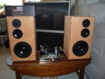
    On a side note, I have to say this amp sounds better than I thought it would. It is driving the midrange section of my homebrew speakers which are open baffle line arrays. The midrange lines came out to about 5.5ohms and are running off of the 4ohm taps. The fresh st-70 makes the temporary tweeter amp sound like absolute garbage. A VERY happy customer here!
    Bob Latino
    Bob Latino
    Admin


    Posts : 3262
    Join date : 2008-11-26
    Location : Massachusetts

    AC Balance Pots On Board Empty Re: AC Balance Pots On Board

    Post by Bob Latino Sat Feb 06, 2010 5:00 pm

    Hi,

    The instructions on how to set the AC balance controls on the VTA driver board are below. Unless you have the proper equipment you should just leave them alone at their "center" positions.

    Bob

    Setting AC Balance on the VTA driver board
    Note – Do not attempt to set the AC balance on this amp unless you have the following …

    1. A Function generator or a signal generator capable of providing a 100 Hz signal to the amp’s input jacks
    2. A Digital multimeter (DMM)
    3. A .10 Mfd @ 100 volt or higher voltage capacitor
    4. Two non inductive 8 ohm resistors 20 watts or higher

    The AC balance controls are the small potentiometers that you soldered in on the BOTTOM of the VTA driver board (one for each channel). Setting each potentiometer as outlined in the driver board assembly manual when you assembled the board will give you an AC balance that is close to optimum. If you have the equipment listed above and you want to reset or peak the AC balance for each pair of output tubes then read below ….

    Be sure your speakers aren't connected during this test, as they could be damaged. Also, I recommend you make up two DMM test leads with a 0.1uf 100 volt or higher rated capacitor in series with each lead. The leads plug into your DMM, and the caps block DC. This allows you to do the AC balance readings on the meter's AC ranges.

    Allow the amp to warm up for at least 15 minutes and then first set the normal DC bias for each output tube with the DC bias potentiometers on the TOP of the driver board.
    1. Connect an 8 ohm, 20 watt (or higher wattage) non-inductive resistor between terminals marked "G" and "8" IN PLACE OF THE SPEAKERS on BOTH channels. These may be purchased at Parts Express online.

    2. LEFT CHANNEL - Set your DMM to AC volts, the 2 volt scale is usually fine. Connect one of your DMM leads to pin 8 on V2 and the other lead to pin 8 on V3 (OR connect one DMM lead to EACH of the DC bias measuring terminals on the power takeoff sockets on the front of the amp where you normally measure DC balance for each tube. Polarity is unimportant.) Using a standard interconnect, apply a 100 Hz test signal (at about .30 volt is good) from your function or signal generator to the LEFT channel input jack. To avoid overheating the 8 ohm non-inductive resistors, prolonged testing should be avoided.

    3. Adjust the LEFT CHANNEL AC Balance control until the meter reads as close to zero as possible. It will move around some, you will not get it to zero out completely in most cases but that's normal. Just go for the lowest reading you can get. When you get the lowest reading you are at optimum AC balance for that channel.

    4. Repeat steps 1, 2, and 3 for the RIGHT CHANNEL AC balance on V6 and V7

    5. Your amp is now set for optimum AC balance on both channels
    avatar
    xlr8
    Guest


    AC Balance Pots On Board Empty Re: AC Balance Pots On Board

    Post by xlr8 Sat Feb 06, 2010 6:50 pm

    Thank you very much!!
    avatar
    dyna70


    Posts : 25
    Join date : 2010-03-30
    Location : Hampshire, England

    AC Balance Pots On Board Empty Re: AC Balance Pots On Board

    Post by dyna70 Wed Mar 31, 2010 7:44 pm

    Thanks very much for this helpful guide.

    As I do not have a function generator, I intend to create a test tone CD using a 100Hz tone using Adobe Audition. I have a few options when I do this, and am not sure which to use: Do I need to set it to a sine or square wav? I haven't a clue unfortunately!

    I guess I also need to work out at what volume level to create this file with? Any ideas?

    Many thanks.

    - John


    P.S. If anyone else is keen on trying this out using Adobe Audition here's the link which explains it: http://help.adobe.com/en_US/Audition/3.0/help.html?content=WS58a04a822e3e5010548241038980c2c5-7f5e.html

    Hi John,

    You want to use a 100 Hz sine wave in this test.

    If you don't have a function generator with a voltage out readout then you might want to try the test at maybe 25% to 50% volume on your computer. Understand that the dummy speaker loads will heat up in a few minutes of testing.

    To all > There is a FREEWARE program that you can run on your computer and output to your ST-70 through the sound card. Download NCH Tone Generator at the link below and run it on your computer. I use connector with a mini stereo plug on the computer end and two RCA connectors to go into the ST-70. The NCH tone generator will output sine, square, sawtooth and other types of waves at different frequencies. Check it out at the link below ..

    NCH Tone Generator

    Bob
    avatar
    dyna70


    Posts : 25
    Join date : 2010-03-30
    Location : Hampshire, England

    AC Balance Pots On Board Empty Re: AC Balance Pots On Board

    Post by dyna70 Fri Apr 09, 2010 8:58 am

    Thanks Bob - and thanks for that link too - nice find! Smile
    mantha3
    mantha3


    Posts : 303
    Join date : 2010-11-10

    AC Balance Pots On Board Empty Re: AC Balance Pots On Board

    Post by mantha3 Sun Dec 12, 2010 11:41 am

    I'd like to do this on my ST120. The steps are clear and I know I need to work with care under the hood.

    Question - For the ST120, is the non inductive 8 ohm resistors 20 watt enough? I know this is a speaker dummy load and I was wondering if I need to go above the 20 Watt as the 120 puts out more Wattage VS an ST70.

    I can only get the non inductive 8 ohm resistors in 20 watt as that is all the local Radio Shack has in stock... Otherwise I can order online which is fine.

    Bob Latino
    Bob Latino
    Admin


    Posts : 3262
    Join date : 2008-11-26
    Location : Massachusetts

    AC Balance Pots On Board Empty Re: AC Balance Pots On Board

    Post by Bob Latino Sun Dec 12, 2010 1:11 pm

    You can use that 20 watt Radio Shack resistor but be careful as mentioned not to test more than a couple of minutes because the two resistors will heat up quickly.

    Personally I don't recommend going through the procedure because it will not (IMHO) enhance the sound quality of your amp in any way that you can really hear. If you set the AC balance control in the center of its rotation as outlined in the board assembly manual, you will be sending half the audio signal for that channel to each output tube. You do this on the assumption that the DC balance controls (bias pots) are set (first) on each tube so that both output tubes of that pair are passing the same amount of current. If you change either or both output tubes of the pair then technically you would have to reset the DC and AC balance again. The AC balance control is put on the BOTTOM of the driver board so that the operator of the amp won't accidentally adjust it off its center position.

    Bob
    Blitzen
    Blitzen


    Posts : 63
    Join date : 2009-07-10

    AC Balance Pots On Board Empty Re: AC Balance Pots On Board

    Post by Blitzen Sun Dec 12, 2010 6:09 pm

    Thanks, Bob. I was just at this point in my build (meaning it's done!) and had everything for this tweak except for the 0.1uf caps. If it's really not worth the effort, I don't think I'll do it...though then there's the question of why those pots are there in the first place?
    The amp is sounding great as is, by the way!
    -Brian
    mantha3
    mantha3


    Posts : 303
    Join date : 2010-11-10

    AC Balance Pots On Board Empty Re: AC Balance Pots On Board

    Post by mantha3 Sun Dec 12, 2010 9:44 pm

    I just did this on my amp. Kind of a pain in the rear. My digital multi meter was doing some strange things I think. The Auto feature was a little erratic. Bob is right and this didn't change the sound. Still sounds awesome!, but didn't make any improvement in sound

    I think I did this right. The meter reading fluctuates when you are doing this. I got it to a point where if I went clockwise or counter clockwise on the balance pot the reading would go up. The readings on the meter jump around. It isn’t like setting the bias where the reading is a bit more constant (compared to this process). So you kind of second guess a bit when doing this.

    Looking back I think I’d have left the balance pot at the 50/50 setting I had it at from the install… Just not mess with it.

    I think you just need one .10mfd / 100Volt capacitor for this… I had one end of the capacitor going to the pin 8 on V2 and then the other end of the cap to the digital multi meter (red probe). I then had the black digital multi meter lead going to the pin 8 on V3 (No cap involved). I just mention this because I was wondering if I needed a second cap to run the digital multi meter black (thru the cap) to the pin 8 V3. Let me know if I'm off on this and needed the 2nd cap??

    The newbie... Laughing Laughing rendeer

    Sponsored content


    AC Balance Pots On Board Empty Re: AC Balance Pots On Board

    Post by Sponsored content


      Current date/time is Fri Apr 19, 2024 11:38 am