The Dynaco Tube Audio Forum

Would you like to react to this message? Create an account in a few clicks or log in to continue.
The Dynaco Tube Audio Forum

Dedicated to the restoration and preservation of all original Dynaco tube audio equipment - Customer support for Tubes4hifi VTA tube amp and preamp kits and all Dynakitparts.com products


+5
Bob Latino
Peter W.
peterh
j beede
Kinski
9 posters

    ST-70 Voltage Help & Introduction

    avatar
    Kinski


    Posts : 43
    Join date : 2017-09-20

    ST-70 Voltage Help & Introduction Empty ST-70 Voltage Help & Introduction

    Post by Kinski Wed Sep 20, 2017 11:14 am

    Hi there! This is my first time posting here. I'm a guitarist living in Brooklyn, NY. I've built LOTS of guitar pedals, some solid state amps, and a Fender 5E3 clone. So electronics are not totally new to me. But I have LOTS to learn. Especially when it comes to Hi-Fi systems. I look forward to learning a lot here. Thanks ahead of time for any and all help and advice.

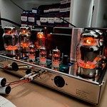
    Long story short, I was just given a Dynaco ST-70 and PAS-2. All original, tubes and all. I've been going through and cleaning it up a bit. I added 1uf output caps to the PAS-2. And changed out the Selenium for diodes in both the ST-70 and PAS-2. THATS IT. I have not replaced a single cap or resistor.

    As far as I can tell from ear and eyes, the amps sounds wonderful. However...

    I decided to check voltages on the ST-70 today. I would be very grateful if someone here could look over these readings and see if they see anything alarming. And if so, what the best solution would be to fix it.

    Thanks again for any and all help/advice.

    EL34 RIGHT CHANNEL

    1 = 1.44 DC
    2 = 3.08 DC
    3 = 427 DC
    4 = 428 DC
    5 = -36 DC
    6 = -36 DC
    7 = 3.11 DC
    8 = 1.44 DC

    EL34 LEFT CHANNEL

    1 = 1.67 DC
    2 = 4.55 DC
    3 = 425 DC
    4 = 429 DC
    5 = -31 DC
    6 = -31 DC
    7 = 4.25 DC
    8 =  1.67 DC

    GZ34

    2 = 441 DC
    4 = 369 AC
    6 = 369 AC
    8 = 441 DC

    QUAD CAP

    SECTION 1 = 439 DC
    SECTION 2 = 429 DC
    SECTION 3 = 378 DC
    SECTION 4 = 294 DC


    Last edited by Kinski on Wed Sep 20, 2017 1:28 pm; edited 1 time in total
    j beede
    j beede


    Posts : 473
    Join date : 2011-02-07
    Location : California

    ST-70 Voltage Help & Introduction Empty Re: ST-70 Voltage Help & Introduction

    Post by j beede Wed Sep 20, 2017 12:45 pm

    Most of those values look like they could have been copied right from the Dynaco voltage chart. Nice. Do you have the assembly manual for the ST-70?

    How are you setting the bias in your amp? I am wondering why you report different voltage drops across your left and right channel 15.6 Ohm cathode resistors. Replacing the Selenium stack with silicon diodes might require resetting the "center point" in the divider that includes the bias pot in order to set the bias current that you want.
    avatar
    Kinski


    Posts : 43
    Join date : 2017-09-20

    ST-70 Voltage Help & Introduction Empty Re: ST-70 Voltage Help & Introduction

    Post by Kinski Wed Sep 20, 2017 1:10 pm

    Hi, thanks for your response!

    I checked the bias and RIGHT was 1.48v. LEFT was 1.35v. Oops, that would probably explain the differences, no? I set the bias a few days ago and didn't check them again before I took these readings.

    Two readings seem off according to a chart I recently found. I'm assuming the chart has ideal voltages. But I don't know.

    Chart says Pin 1 of the EL34s should be about 0.4v. My readings are higher than that.
    Also...
    The chart says Quad Cap Section 4 should be 380 to 430 DC. My reading is pretty low, no?


    As far as being able to set bias, there is plenty of swing in the pots for proper biasing.

    I do have ALL the original documentation for both ST and Pas units. Even the sales receipts!


    Last edited by Kinski on Wed Sep 20, 2017 2:51 pm; edited 1 time in total
    peterh
    peterh


    Posts : 1833
    Join date : 2012-12-25
    Location : gothenburg, sweden

    ST-70 Voltage Help & Introduction Empty Re: ST-70 Voltage Help & Introduction

    Post by peterh Wed Sep 20, 2017 1:26 pm

    You "added 1uf output caps to the ST-70" ??

    Did you add this as output cap in the PAS2 ( thats good) or as input cap in ST70 ( also good).

    But i don't think you added it as output cap in the ST70 !
    avatar
    Kinski


    Posts : 43
    Join date : 2017-09-20

    ST-70 Voltage Help & Introduction Empty Re: ST-70 Voltage Help & Introduction

    Post by Kinski Wed Sep 20, 2017 1:28 pm

    Hi, sorry, i mistyped. The 1uf output caps were added to the PAS-2! NOT the ST-70! Thanks! I'll edit my top post.


    Last edited by Kinski on Wed Sep 20, 2017 2:50 pm; edited 1 time in total
    Peter W.
    Peter W.


    Posts : 1351
    Join date : 2016-08-07
    Location : Melrose Park, PA

    ST-70 Voltage Help & Introduction Empty Re: ST-70 Voltage Help & Introduction

    Post by Peter W. Wed Sep 20, 2017 2:22 pm

    Lots of good advice so far. Some *very basics* on these beasts:

    Other than to check for obvious run-away conditions, do not set bias until the unit has been running for at least 15 minutes. Set it then, wait 1/2 hour, then check it again. Use a decent meter, and check the reading of the meter against a standard NEW carbon-zinc D-battery if you can find one. Those read Exactly 1.56 VDC. Most alkaline batteries read about 1.6V, so you will not be able to match exactly, but you will be able to understand the accuracy of your meter.

    If you have 'done' other sorts of amplifiers, you will likely have, or understand in concept, an ESR meter. Use it on the filter and bias (all electrolytic) caps, at least.

    If you have changed the selenium diode, please do the resistor mod on the bias supply resistors so that the bias adjustments will be brought back into the center-range of the adjustment controls (on the 70). There is a sticky on just this.

    Yes, adding a small-value (up to 1 uF) 600 V film cap across the filter caps (per cap) is a good idea. Be careful that you do not create any shorts in the process.

    Again, as one schooled in tube amps, you understand that there are lethal voltages on top and underneath that amp. Be careful!

    Enjoy!
    avatar
    Kinski


    Posts : 43
    Join date : 2017-09-20

    ST-70 Voltage Help & Introduction Empty Re: ST-70 Voltage Help & Introduction

    Post by Kinski Wed Sep 20, 2017 3:54 pm

    Ok, thanks so much for all the help so far. I have a new question regarding the ST-70.

    Sadly, it seems one of the original Sylvania EL34 tubes is bad. It tends to red-plate BADLY if bumped in just the right way. And makes loud short staticky sounds when tapped. These issues follow the tube when swapped to a different location.

    So it looks like it has to go. I should probably take out the other EL34 in that channel and put in a matched pair. If so, I have a matched pair of lightly used SED Winged C EL34 that need a home.

    Also, I'd really love to keep the other original Sylvania pair on the other channel. Is there any reason I should not do this? I guess technically the subtle differences between the two tube brands would play out in their own channel, but I think I can live with that.

    Thoughts on this?
    Peter W.
    Peter W.


    Posts : 1351
    Join date : 2016-08-07
    Location : Melrose Park, PA

    ST-70 Voltage Help & Introduction Empty Re: ST-70 Voltage Help & Introduction

    Post by Peter W. Wed Sep 20, 2017 4:51 pm

    Kinski wrote:Ok, thanks so much for all the help so far. I have a new question regarding the ST-70.

    Sadly, it seems one of the original Sylvania EL34 tubes is bad. It tends to red-plate BADLY if bumped in just the right way. And makes loud short staticky sounds when tapped. These issues follow the tube when swapped to a different location.

    So it looks like it has to go. I should probably take out the other EL34 in that channel and put in a matched pair. If so, I have a matched pair of lightly used SED Winged C EL34 that need a home.

    Also, I'd really love to keep the other original Sylvania pair on the other channel. Is there any reason I should not do this? I guess technically the subtle differences between the two tube brands would play out in their own channel, but I think I can live with that.

    Thoughts on this?

    YIKES!!

    Minor Rant Warning:

    a) Turn off and unplug the amp and allow it to cool for 24 hours.
    b) Obtain a couple of dental-picks, some Q-Tips, extremely high-proof *isopropyl alcohol* and some old fashioned *round* toothpicks.
    c) Find a workbench (or kitchen table) with excellent, shadow-free lighting.
    d) Remove all tubes and mark their locations on the amp (and the tubes).
    e) Remove the cage and bottom plate.

    Now, working over a towel, thick rag or similar, you are going to clean and tension all the tube sockets. First rinse them down with the Alcohol (91% minimum, 100% if you can find it). I use a rechargeable compressed air spray can so as to get some force behind it when rinsing. The amp is unplugged and cold, you are working over a towel, so unless you are a smoker, there is little danger here.

    Then, using the round tooth-picks (which you have soaking in alcohol), you will lightly clean out the tube sockets. The wood will burnish to a small degree and do no damage and leave no metal shavings behind. If you happen to have burnishing files (a specialty Jeweler's item) you may use them, carefully. On the 9-pin sockets, do not push in too hard. Be VERY careful.

    Then, using the dental picks, you will carefully tighten each socket by pulling the individual contacts in each individual pin socket back towards the center. Carefully, slowly, take your time. Keep in mind that these sockets are many years old, made from tin-plated bronze, and  have been thoroughly annealed over the years. They are *SOFT* and *LOOSE*.

    Rinse again with alcohol. Use the Q-Tips on the bottom and see if any skunge comes off. If so, keep rinsing until it comes clean.

    Then using a coarse Scotch-Brite pad, clean off the tube pins, also using alcohol. Check for any loose bases. If there are any, DO NOT use super-glue to repair them. The stuff dries so hard that it has been known to cause the glass to fracture from thermal stress. Use a hard temperature-resistant epoxy such as JB-Weld or similar in small, careful amounts.

    On the Wonky tube, touch up each pin with the soldering iron and add a bit of solder. Hold the tube upside down when doing this and flow a *small* amount of solder into each pin. We are looking to correct any separated leads.

    When everything is nice and clean - and tight - re-assemble and reinstall the tubes. Bias as directed. I suspect that the red-plate issue will have gone away.

    These are very basic maintenance items on any piece of tube equipment new to the stable. Kinda-sorta like isolating a new kitten or puppy until it has had its shots and is wormed. I do this stuff on anything new even before I apply power for the first time. Having done it so often, it would take me less than an hour on the 70, even if truly filthy.

    While you are there, also check every wire connection (both ends) on the tube sockets. Use the dental picks to give each connection a bit of a tug. Back when old-fashioned clamp-type one-size-fits-all wire strippers were used, wires got nicked - and nicked wires will crack at the nick causing frustrating and often invisible intermittents. And, examine the traces on the circuit boards very carefully. Sometimes thermal stresses cause the traces to crack. Reflow any that look suspicious, and use a strand of fine wire over the suspected gap as "rebar".

    Above all, enjoy!


    Last edited by Peter W. on Wed Sep 20, 2017 5:03 pm; edited 1 time in total (Reason for editing : Added advice on checking connections and traces.)
    avatar
    Kinski


    Posts : 43
    Join date : 2017-09-20

    ST-70 Voltage Help & Introduction Empty Re: ST-70 Voltage Help & Introduction

    Post by Kinski Wed Sep 20, 2017 5:05 pm

    Hi, thanks for the detailed response! I cleaned a lot of the amp a few days ago using denatured alcohol. I did not however tension all of the tube sockets as you suggested. I will say the tubes feel pretty secure in their sockets so I'm not too worried about those, but I'll take a closer look to be sure.

    I have the amp biased around 1.25v

    I'll look into the idea of flowing solder into the tube pins. The faulty tube has a small high pitch rattle sound when gently shaken. Similar to the sound when shaking a burned out light bulb. The other 3 EL34's do not have this sound.

    I did just notice as well that one of the other tubes in the other channel has a very small amount of steady red-plating too. A small spot with a faint red glow.

    The BAD tube I mentioned previously will be just fine and then ALL OF A SUDDEN GLOW FIRE RED. And a loud hum can be heard. If I gently bump it with my finger it all goes away.
    Peter W.
    Peter W.


    Posts : 1351
    Join date : 2016-08-07
    Location : Melrose Park, PA

    ST-70 Voltage Help & Introduction Empty Re: ST-70 Voltage Help & Introduction

    Post by Peter W. Wed Sep 20, 2017 5:15 pm


    The BAD tube I mentioned previously will be just fine and then ALL OF A SUDDEN GLOW FIRE RED. And a loud hum can be heard. If I gently bump it with my finger it all goes away.[/quote]

    That which can be cured by impact = intermittent. If outside the tube guts, therefore fixable. If inside the tube guts (and if the alternative is landfill), try tapping the tube *UPSIDE DOWN* sharply on a wooden board with a towel between the glass and the board. Not to break the glass, but to dislodge any stuff. Then gently roll the tube upright so the 'stuff' does not fall back down inside the guts, but falls outside to the base.
    Bob Latino
    Bob Latino
    Admin


    Posts : 3263
    Join date : 2008-11-26
    Location : Massachusetts

    ST-70 Voltage Help & Introduction Empty Re: ST-70 Voltage Help & Introduction

    Post by Bob Latino Wed Sep 20, 2017 5:25 pm

    Kinski wrote:

    I have the amp biased around 1.25v

    The BAD tube I mentioned previously will be just fine and then ALL OF A SUDDEN GLOW FIRE RED. And a loud hum can be heard. If I gently bump it with my finger it all goes away.

    Biasing an original Dynaco ST-70 @ 1.25 VDC for each pair of output tubes will give a bias current of about 40 milliamps per each output tube. This is a wise choice. Dynaco biased the amps (1.56 vdc) at 50 milliamps per each output tubes which was probably OK for those sturdy Mullard EL34 output tubes of the 1960's. Modern EL34's are less "robust" than the older Mullards and are better off at the lower bias setting.

    If you tap the tube and and the hum goes away, this is almost assuredly a contact issue with the tube socket pin and the tube pin. (most likely pin #5 where the bias voltage is injected into the tube). Clean all the tube pins on that socket and "retension" them. Use a small jewelers screwdriver to make the opening on each socket pin smaller.

    Bob
    corndog71
    corndog71


    Posts : 840
    Join date : 2013-03-19
    Location : It can get windy here

    ST-70 Voltage Help & Introduction Empty Re: ST-70 Voltage Help & Introduction

    Post by corndog71 Wed Sep 20, 2017 5:47 pm

    I would recommend a fresh set of tubes. Then again I would also recommend the VTA driver circuit and a new power transformer. I can appreciate the vintage gear but evolution is a good thing.
    avatar
    Kinski


    Posts : 43
    Join date : 2017-09-20

    ST-70 Voltage Help & Introduction Empty Re: ST-70 Voltage Help & Introduction

    Post by Kinski Wed Sep 20, 2017 8:06 pm

    Thanks for all of the input!

    Corndog, yeah, I’m aware of all new upgrades available for these things. Thanks for the suggestion. I may do some of the upgrades down the line. But for now I’m really enjoying the sound as is. I am curious about the VTA Driver though. I noticed it has a bias for each tube. Would this allow you to use unmatches tubes?

    Bob and Peter, thanks for all the detailed responses! Tomorrow I will clean the socket pins and see what comes of it. I could very well be wrong, but I really feel like it’s the tube that is faulty, and not the socket. My reasons for that is because that one tube has the same issue no matter what socket I put it into. And no other tubes behave this way in that socket.

    As a test, I put in the SED Winged C pair in that channel. I’ve been listening for a few hours now, and it’s completely solid. No issues. And sounds great! I maybe hear a few differences with those tubes, but it’s hard to know how much is real and how much I’m just imagining.

    That being said, I’m hopeful what you suggeststed will cure the red-plating. I’ll post an update with the results.
    avatar
    Kinski


    Posts : 43
    Join date : 2017-09-20

    ST-70 Voltage Help & Introduction Empty Re: ST-70 Voltage Help & Introduction

    Post by Kinski Thu Sep 21, 2017 10:46 am

    I cleaned up the tube socket a bit more and then tightened the pin sockets with a small screwdriver, as you guys suggested and put the suspect tube back in place. I also cleaned and very lightly sanded the pins of the EL34 tube, just in case there was any corrosion on the tube itself.

    WOW WOW WOW! I'm happy to say its been running for about 40 min now with no issue. I've even tried to get it to misbehave a bit by gently knocking and tapping the tube. Its dead silent. I'll keep an eye on it today to make sure, but all is looking well. I'd buy you all a beer if I could.

    One of the other EL34s is still very lightly red-plating. No noise issues, but has the faintest red glow about the size of a pea. No adjustments change the red-plating. Its very steadily just there. Any ideas on that one?
    Peter W.
    Peter W.


    Posts : 1351
    Join date : 2016-08-07
    Location : Melrose Park, PA

    ST-70 Voltage Help & Introduction Empty Re: ST-70 Voltage Help & Introduction

    Post by Peter W. Thu Sep 21, 2017 11:08 am

    Same treatment on all sockets. Careful attention to that red-plating tube moving forward.

    Do you have the means to test tubes (on a tester)? It would be good to know where they come out on the scale from new-to-dead.
    avatar
    Kinski


    Posts : 43
    Join date : 2017-09-20

    ST-70 Voltage Help & Introduction Empty Re: ST-70 Voltage Help & Introduction

    Post by Kinski Thu Sep 21, 2017 1:15 pm

    Sadly, I don't own a tube tester or an ESR Meter.
    I didn't make it clear in my last post, but I did the same treatment to all tubes and tube sockets.

    Also, I took the voltages on the PAS-2 and they are pretty much a perfect match with the Dynaco manual. All seems to be running as it should now. I won't let my guard down on the ST-70 power tubes for a few more days, just to be safe.

    Thanks again to all who helped me out. I really do appreciate it!
    deepee99
    deepee99


    Posts : 2244
    Join date : 2012-05-23
    Location : Wallace, Idaho

    ST-70 Voltage Help & Introduction Empty Re: ST-70 Voltage Help & Introduction

    Post by deepee99 Thu Sep 21, 2017 2:35 pm

    Kinski wrote:Thanks for all of the input!

    Corndog, yeah, I’m aware of all new upgrades available for these things. Thanks for the suggestion. I may do some of the upgrades down the line. But for now I’m really enjoying the sound as is. I am curious about the VTA Driver though. I noticed it has a bias for each tube. Would this allow you to use unmatches tubes?

    Bob and Peter, thanks for all the detailed responses! Tomorrow I will clean the socket pins and see what comes of it. I could very well be wrong, but I really feel like it’s the tube that is faulty, and not the socket. My reasons for that is because that one tube has the same issue no matter what socket I put it into. And no other tubes behave this way in that socket.

    As a test, I put in the SED Winged C pair in that channel. I’ve been listening for a few hours now, and it’s completely solid. No issues. And sounds great! I maybe hear a few differences with those tubes, but it’s hard to know how much is real and how much I’m just imagining.

    That being said, I’m hopeful what you suggeststed will cure the red-plating. I’ll post an update with the results.

    Tube pin diameters vary quite widely. I took my digital micrometer to a few of both various brands and types of output tubes and was surprised by the differences, even amongst the same manufacturers of the same tube . Could be that the SEDs have "fatter" pins than your old ELs, thus making a better contact. I would take PeterW's advice and re-tension all the socket holes and clean them as he prescribes. Fat tube pins will widen the socket holes and invite trouble if you put some skinnier ones back in, unless you retention them first.
    Wish we could just solder the suckers in. The tube-socket connexion is the Achilles Heel of tube gear and must be paid attention to.
    avatar
    Kinski


    Posts : 43
    Join date : 2017-09-20

    ST-70 Voltage Help & Introduction Empty Re: ST-70 Voltage Help & Introduction

    Post by Kinski Thu Sep 21, 2017 11:22 pm

    My ST-70 bias readings start out quite high when I first turn the amp on (1.7v - 1.8v), and then over 30 min they lower to about where they should be. Is this normal?
    deepee99
    deepee99


    Posts : 2244
    Join date : 2012-05-23
    Location : Wallace, Idaho

    ST-70 Voltage Help & Introduction Empty Re: ST-70 Voltage Help & Introduction

    Post by deepee99 Fri Sep 22, 2017 2:40 am

    Kinski wrote:My ST-70 bias readings start out quite high when I first turn the amp on (1.7v - 1.8v), and then over 30 min they lower to about where they should be. Is this normal?
    Yes. Except for an extreme anomaly on start-up, don't sweat the bias readings until the amp is fully warmed up, 30 minutes minimum. You'll get the nominal reading about two hours after start-up.
    Tubes4ever
    Tubes4ever


    Posts : 167
    Join date : 2015-07-14
    Location : Star, Idaho

    ST-70 Voltage Help & Introduction Empty Re: ST-70 Voltage Help & Introduction

    Post by Tubes4ever Fri Sep 22, 2017 4:44 pm

    Kinski wrote:I cleaned up the tube socket a bit more and then tightened the pin sockets with a small screwdriver, as you guys suggested and put the suspect tube back in place. I also cleaned and very lightly sanded the pins of the EL34 tube, just in case there was any corrosion on the tube itself.

    WOW WOW WOW! I'm happy to say its been running for about 40 min now with no issue. I've even tried to get it to misbehave a bit by gently knocking and tapping the tube. Its dead silent. I'll keep an eye on it today to make sure, but all is looking well. I'd buy you all a beer if I could.

    One of the other EL34s is still very lightly red-plating. No noise issues, but has the faintest red glow about the size of a pea. No adjustments change the red-plating. Its very steadily just there. Any ideas on that one?

    I had an EL34 that had a dim red glow along the seam of the plate only on one side of the tube when it was biased properly.
    It worked and sounded good. You're probably okay using it.
    avatar
    Kinski


    Posts : 43
    Join date : 2017-09-20

    ST-70 Voltage Help & Introduction Empty Re: ST-70 Voltage Help & Introduction

    Post by Kinski Wed Sep 27, 2017 9:18 pm

    Thank you all. I replaced the lamp with an LED today. I’m thinking of replacing the cap cans in both the PAS-2 and ST-70. I’m aware I can buy replacement can caps. But, can’t I just buy 4 individual caps and run the wires from the 4 “can cap” lugs to the individual caps instead. Then send all negative sides to ground?
    avatar
    Kinski


    Posts : 43
    Join date : 2017-09-20

    ST-70 Voltage Help & Introduction Empty Re: ST-70 Voltage Help & Introduction

    Post by Kinski Wed Sep 27, 2017 9:32 pm

    Also, how would I install a fuse?
    Peter W.
    Peter W.


    Posts : 1351
    Join date : 2016-08-07
    Location : Melrose Park, PA

    ST-70 Voltage Help & Introduction Empty Re: ST-70 Voltage Help & Introduction

    Post by Peter W. Thu Sep 28, 2017 5:00 pm

    Kinski wrote:Also, how would I install a fuse?

    http://triodeelectronics.com/st70capupgrade.html Cap board for the ST70 One of MANY - please do not take this as an endorsement. Just a point of departure.

    http://triodeelectronics.com/sdslacabofor1.html Same for PAS devices - same caveat. Note the on-board fuse.

    Use the on-board fuse for the 70.

    Hope this helps.

    NOTE: If you can find a board for the PAS that eliminates the 12X4, you will reduce the load on the power-transformer - which is a very good thing.
    avatar
    Kinski


    Posts : 43
    Join date : 2017-09-20

    ST-70 Voltage Help & Introduction Empty Re: ST-70 Voltage Help & Introduction

    Post by Kinski Thu Sep 28, 2017 9:05 pm

    Thanks for the info! For the PAS and ST-70, I think I’m going to just replace the can cap with a new one. And I’ve already modified the selenium rectifiers. So I’d just like to simply add a fuse. What would be the best way to do this to the PAS-2? Should a fuse be added to the ST-70 as well?
    Peter W.
    Peter W.


    Posts : 1351
    Join date : 2016-08-07
    Location : Melrose Park, PA

    ST-70 Voltage Help & Introduction Empty Re: ST-70 Voltage Help & Introduction

    Post by Peter W. Fri Sep 29, 2017 10:30 am

    Kinski wrote:Thanks for the info! For the PAS and ST-70, I think I’m going to just replace the can cap with a new one. And I’ve already modified the selenium rectifiers. So I’d just like to simply add a fuse. What would be the best way to do this to the PAS-2? Should a fuse be added to the ST-70 as well?

    http://www.littelfuse.com/products/fuse-blocks-fuseholders-and-fuse-accessories/electrical-inline-panel-mount-fuse-holders/571.aspx

    There are a number of options. If you have already done the silicon diode replacement, and (hopefully) gone to smaller capacitors, you could punch a hole in the back panel for a standard fuse-holder. This is the most convenient option as you will have access from the outside. But requires a bit of trouble on your part.

    http://www.littelfuse.com/products/fuse-blocks-fuseholders-and-fuse-accessories/fuse-blocks/254.aspx

    Writing for myself, one of these inside mounted to the chassis fills the need nicely. A bit of trouble to access, but if that becomes a serious problem, either you are using the wrong fuses or have a problem with the equipment.

    Now, for the 70, use the existing fuse, and make sure you are using (at least) the correct *DUAL ELEMENT* 3A fuse as was supplied by Dynaco. Again, writing for myself, I operate with a 2A dual-element fuse that has worked just fine for years. It pulls no more than about 1.4A+/- at full volume, so a 2A DE Fuse does just fine.

    Sponsored content


    ST-70 Voltage Help & Introduction Empty Re: ST-70 Voltage Help & Introduction

    Post by Sponsored content


      Current date/time is Tue May 07, 2024 8:28 pm