The Dynaco Tube Audio Forum

Would you like to react to this message? Create an account in a few clicks or log in to continue.
The Dynaco Tube Audio Forum

Dedicated to the restoration and preservation of all original Dynaco tube audio equipment - Customer support for Tubes4hifi VTA tube amp and preamp kits and all Dynakitparts.com products


4 posters

    New to forum looking to rebuild Dynaco Mk 2s and a 3

    MrBlimp
    MrBlimp


    Posts : 45
    Join date : 2018-11-27
    Location : New York

    New to forum looking to rebuild Dynaco Mk 2s and a 3 - Page 2 Empty Re: New to forum looking to rebuild Dynaco Mk 2s and a 3

    Post by MrBlimp Wed Nov 28, 2018 6:24 pm

    PeterCapo wrote:  May I ... suggest avoiding the mistake that some do in concluding the original Dynaco circuit designs don't have the sonic quality to compete with so-called "modern" tube designs.  /

    I haven't decided what to do so far other then clean up the bottoms, and replace the 4 Cap can circuits.

    I'm open to any and all suggestions.
    MrBlimp
    MrBlimp


    Posts : 45
    Join date : 2018-11-27
    Location : New York

    New to forum looking to rebuild Dynaco Mk 2s and a 3 - Page 2 Empty Re: New to forum looking to rebuild Dynaco Mk 2s and a 3

    Post by MrBlimp Wed Nov 28, 2018 7:40 pm

    I also have to figure out what is going on with the miss matched pair of tubes in the amp with the larger board (previously referred to as "Mk2-#1") as I don't remember running it that way.

    I do have a box of tubes that I haven't looked at yet so these might be some sacrificial ones I had in there from back when I last thought about getting these amps working.

    I also have a (blown) original Quad Cap which I always intended to remount (my intention has always been to install replacement capacitors underneath) in order to make the amps look as original as possible for a up top view.

    New to forum looking to rebuild Dynaco Mk 2s and a 3 - Page 2 <a href=New to forum looking to rebuild Dynaco Mk 2s and a 3 - Page 2 IMG-7632" />


    Last edited by MrBlimp on Thu Dec 06, 2018 3:00 pm; edited 5 times in total
    avatar
    Guest
    Guest


    New to forum looking to rebuild Dynaco Mk 2s and a 3 - Page 2 Empty Re: New to forum looking to rebuild Dynaco Mk 2s and a 3

    Post by Guest Wed Nov 28, 2018 7:46 pm

    .


    Last edited by PeterCapo on Mon Nov 30, 2020 7:39 pm; edited 1 time in total
    WLT
    WLT


    Posts : 186
    Join date : 2013-07-13
    Location : Rochester NY

    New to forum looking to rebuild Dynaco Mk 2s and a 3 - Page 2 Empty Re: New to forum looking to rebuild Dynaco Mk 2s and a 3

    Post by WLT Wed Nov 28, 2018 9:36 pm

    From looking at your write up on your testing you have some OK things and some issues. Some of your write up is difficult for me to follow so I may come back with more comments after I figure more of this out. If you look at the published MK II schematic you will find 1) there is no .02 cap from 6.3 V center tap winding to ground connection. 2) the 6.3V center tap winding is connected directly to ground, 3) there is one 100uF cap in the bias supply not two (or single) 47uF, 4) You refer to a choke but it is just a 50 ohm 10 watt resistor. Agreed?

    A few comments on your readings. All four brown, black, red resistors (on each tube) are to be 1000 ohms and are way high. All should be replaced. The discolored 50 ohm 10 watt resistor is probably OK as it reads OK. The resistor on the speaker terminals is blue, grey (not lt blue), brown but it is in parallel with the output transformer winding. Together they will be in the 1ohm or so area. That resistor is usually not a problem and is hardly worth unsoldering to measure.

    A few concerns on your write up. Quad cap resistor should be blue, grey, red which is 6800 ohms. Not blue, lt blue, red and should not read 789. It may have faded but the value is low. Please double check. The bias pot resistor to ground you stated is brown, black, red. That is 1000 ohm but it should be brown, black , orange which is 10,000 ohms. Please double check. For the bias circuit test resistance from the diode to ground thru each resistor (1 K , pot, 10K). If the pot is 5K you have a total of 16K. If it is a 10K pot your total is 21K. Make sure they all add up properly – or at least close.

    I will reread but I will be out of town tomorrow so I may run out of time.
    MrBlimp
    MrBlimp


    Posts : 45
    Join date : 2018-11-27
    Location : New York

    New to forum looking to rebuild Dynaco Mk 2s and a 3 - Page 2 Empty Re: New to forum looking to rebuild Dynaco Mk 2s and a 3

    Post by MrBlimp Wed Nov 28, 2018 10:58 pm

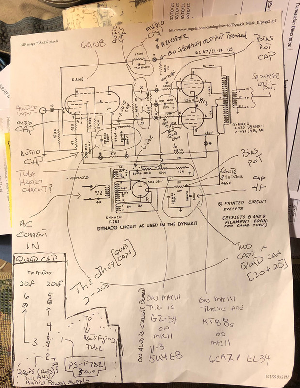
    WLT wrote:From looking at your write up on your testing you have some OK things and some issues. Some of your write up is difficult for me to follow so I may come back with more comments after I figure more of this out.  If you look at the published MK II schematic you will find 1) there is no .02 cap from 6.3 V center tap winding to ground connection. 2) the 6.3V center tap winding is connected directly to ground, 3) there is one 100uF cap in the bias supply not two (or single) 47uF, 4) You refer to a choke but it is just a 50 ohm 10 watt resistor. Agreed?

    1) Yes, agreed - no .02 Cap on the Mk2 but I read somewhere that it was a good idea to install one - is that not the case?
    2) The center tap (from the P782) of both amps is grounded at the ground strip, is directly bridged to the other P782 lead on that strip, while also going to the speaker terminal where it connects with the Black lead from the A431. This is extremely identical to the Mk3 circuit with the exception of the direct bridge in the place of the .02 Cap.
    3) Bias supply Cap - You state the Cap should be 100uF - on both amps there is only a 47uF 100v Cap (I already saw this as something to be addressed/corrected)
    4) Yes, agreed - I used the term "choke" as back in my younger years we often called that resistor when used with a speaker crossover a choke.

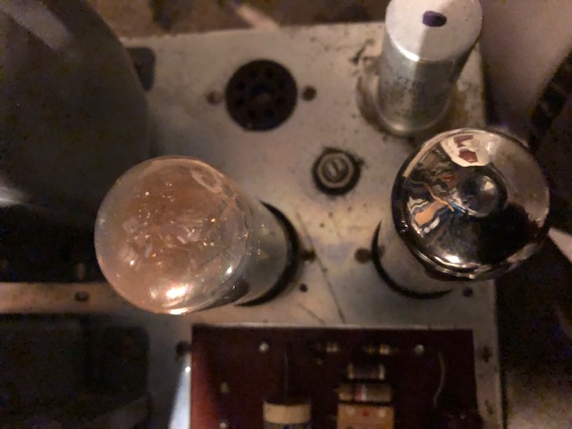
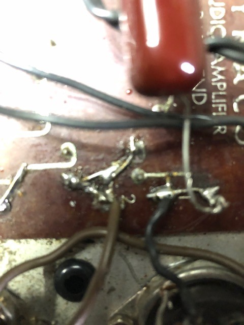
    WLT wrote:A few comments on your readings. All four brown, black, red resistors (on each tube) are to be 1000 ohms and are way high. All should be replaced.

    I was expecting to have to replace the 4.

    WLT wrote:The discolored 50 ohm 10 watt resistor is probably OK as it reads OK.

    I figured as much but I may change it anyway given I have to do a lot of work in that corner of the unit.

    WLT wrote:The resistor on the speaker terminals is blue, grey (not lt blue), brown but it is in parallel with the output transformer winding. Together they will be in the 1ohm or so area. That resistor is usually not a problem and is hardly worth unsoldering to measure.

    Good to know.

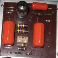
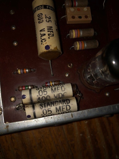
    WLT wrote:A few concerns on your write up. Quad cap resistor should be blue, grey, red which is 6800 ohms. Not blue, lt blue, red and should not read 789. It may have faded but the value is low. Please double check. The bias pot resistor to ground you stated is brown, black, red. That is 1000 ohm but it should be brown, black , orange which is 10,000 ohms. Please double check. For the bias circuit test resistance from the diode to ground thru each resistor (1 K , pot, 10K). If the pot is 5K you have a total of 16K. If it is a 10K pot your total is 21K. Make sure they all add up properly – or at least close.

    I was just sitting down, post dinner, to review, what I found, against the schematic and parts list to see if I found what I thought I had. Especially as the colors on the resistors are a combination of faded and aged and were hard to distinguish clearly. I didn't think "light Blue" sounded correct and the red of the brown, black, red looked like it could have been orange.

    So yes the resistor on the quad can for the small board amp is Blue Gray Red (Silver may have faded off) and the one on the large board amp is Blue Gray Red Silver

    This was just my first pass, I'll be rechecking everything a few times before proceeding.

    WLT wrote:I will reread but I will be out of town tomorrow so I may run out of time.

    I greatly appreciate everyone's directions and assistance.

    My first decision, before I found this forum, was to take them to a shop in the Hudson Valley, NY that has experience in repairing them and whom told me they would probably cost about $500.00 each to get in running shape. If things get too involved for me I may still go that route, but first I want to see how far I can take them.


    Last edited by MrBlimp on Thu Nov 29, 2018 2:51 am; edited 7 times in total
    MrBlimp
    MrBlimp


    Posts : 45
    Join date : 2018-11-27
    Location : New York

    New to forum looking to rebuild Dynaco Mk 2s and a 3 - Page 2 Empty Re: New to forum looking to rebuild Dynaco Mk 2s and a 3

    Post by MrBlimp Wed Nov 28, 2018 11:36 pm

    PeterCapo wrote:Looking at your previous posts, I think you have your work cut out for you regardless of which way you go.  You'd certainly want to make sure you are familiar with safe work practices around the potentially lethal voltages in these amps.  That's top priority..

    All the work I plan to do now does not involve powering anything up. The amps have been off for 25 years without the 5U468 tubes, so I don't think I have to worry about voltage right now. Certainly there will be a time when I do. I have had some shock experiences - once in my youth I accidently touched my mouth with a live wire, a couple of times setting up gear on outdoor stages when I was a roadie in my 20s, and I was sloppy on a few occasions in my 30s when I moonlighted from my regular job (driving a school bus) working as an electrician's apprentice - so I now have a very high respect for electricity, especially stored electricity.

    PeterCapo wrote: Options for changing the circuit are more limited for Mark II/III than for the Stereo 70.  Even if you go with a different driver board, it will still rely on the rest of the amp being in a working, more-or-less original configuration.  .... getting the rest of the amp configured properly, so you'd probably want to do that ahead of time, I would think..

    Yes that's my plan. The most I may do now is change some Caps on the top board, but that is all yet to be decided. First is to get everything cleaned up, bad stuff replaced, and everything looking right underneath.

    PeterCapo wrote:Ideally, you'd know what kind of sound qualities you prefer and then rebuild the amp with a circuit that is more likely to get you there.  The question is how to get, in advance, a sense for how the amps will sound depending on which circuit is employed.  The only thing I can think of is to spend a lot of time reading some of the more carefully considered user comments around the Internet to see if a picture emerges that makes sense according to your taste in sonics.

    I haven't even started thinking about this aspect. I still have to decide what to use as a Pre-amp or if I want to invest in getting my Scott 121-Cs working. When the Dynaco system was functional it was used in the basement and garage where I could fit the Voice-of-the-Theater cabinets. My main listening system was a Kenwood KA-7002 solid state amplifier with Bass (300/150Hz) and Treble (6000/2000Hz) DEFEATS that were switch operated which I used to change the sound as the music was playing. The Scott 121-Cs have a load of built in EQ as well.

    I still have the Kenwood but I so rarely use it that the controls are all scratchy; plus, the balance doesn't seem to function properly, and both my turntables need a stylus/cartridge balance/setup.
    WLT
    WLT


    Posts : 186
    Join date : 2013-07-13
    Location : Rochester NY

    New to forum looking to rebuild Dynaco Mk 2s and a 3 - Page 2 Empty Re: New to forum looking to rebuild Dynaco Mk 2s and a 3

    Post by WLT Thu Nov 29, 2018 11:48 am

    The Scott 121 C would be a great mate for the Dynacos. Another project by the sounds of it. One project at a time

    I think you need to resolve which rebuild plan you are going to follow. The .02 cap in the 6.3V winding is an "improvement" Dynaco put in for the MK III. It is better but not significant. My MK IIs are connected to ground without the cap and they work fine. My MK IIIIs have the cap and sound fine. The 12 ohm resistor to the output tubes is correct for the MK II and was changed to 11.2 for the MK III. So it comes back to which rebuild are you going to follow. You do not have the C354 choke in the power supply nor the 6550 or GZ34 tubes to make these into a MK IIIs. You can always buy them but why? There is nothing wrong with rebuilding as MK IIs. Also easier as you are part way there. Some of what you have planned works for either rebuild.
    Peter W.
    Peter W.


    Posts : 1351
    Join date : 2016-08-07
    Location : Melrose Park, PA

    New to forum looking to rebuild Dynaco Mk 2s and a 3 - Page 2 Empty Re: New to forum looking to rebuild Dynaco Mk 2s and a 3

    Post by Peter W. Thu Nov 29, 2018 11:53 am

    I kinda like the step-by-step.

    Thank you!
    MrBlimp
    MrBlimp


    Posts : 45
    Join date : 2018-11-27
    Location : New York

    New to forum looking to rebuild Dynaco Mk 2s and a 3 - Page 2 Empty Re: New to forum looking to rebuild Dynaco Mk 2s and a 3

    Post by MrBlimp Thu Nov 29, 2018 6:51 pm

    WLT wrote: The Scott 121 C would be a great mate for the Dynacos. Another project by the sounds of it. One project at a time.

    Yes, absolutely, but that means I have to have a means to delivering a signal to these amps. Not my preference but I sort of remember coming across a YouTube video in which they were using a iPhone connected to a set of Dynaco tube amps. But it could have been an integrated amplifier not amps.

    WLT wrote: I think you need to resolve which rebuild plan you are going to follow.

    I get the feeling that the bottom end is already half and half (Mk2/Mk3). I've been reviewing the Mk2 schematic that I have but I have never been great following them (they are too abstract for me). I am much better using a wiring diagram, which I haven't found for a Mk2. Same with cars (especially for my vintage sports cars on which I have put in hundreds of hours of electric refreshing).

    WLT wrote: The .02 cap in the 6.3V winding is an "improvement" Dynaco put in for the MK III. It is better but not significant. My MK IIs are connected to ground without the cap and they work fine. My MK IIIIs have the cap and sound fine.

    I guess my question would be "will adding it change the audio in any way?" I don't see how as this is the power circuit not the audio circuit, but I could be mistaken. The next question would be what is the "improvement" benefit that was gained by using a capacitor in place of the bridged ground connection?

    WLT wrote: The 12 ohm resistor to the output tubes is correct for the MK II and was changed to 11.2 for the MK III. So it comes back to which rebuild are you going to follow.

    Given the current, what appears to be, 50/50 state of these amps I think I will just do repairs and replacement of Caps and resistors that need replacement and leave things as they are. Plus, this leads to yet another "what is the improvement benefit" question, and how does it change things? I figure Dynaco made improvements for reasons, but I don't know enough to understand how the changes that they made on the power side affect the audio side.

    WLT wrote: You do not have the C354 choke in the power supply nor the 6550 or GZ34 tubes to make these into a MK IIIs. You can always buy them but why?

    I totally agree and have no intention of buying chokes. Though I would be interested in understanding the benefit the addition of the choke provided that prompted Dynaco to include them.

    WLT wrote: There is nothing wrong with rebuilding as MK IIs. Also easier as you are part way there. Some of what you have planned works for either rebuild.

    My current plan is to perform the couple of issue type repairs (shrink tubing on frayed cord, replacing bad resistors, etc...); replace the Caps that I see as under-rated; and replace the Quad cap (either with new or higher voltage single Caps).

    Then I will determine what to do next.
    MrBlimp
    MrBlimp


    Posts : 45
    Join date : 2018-11-27
    Location : New York

    New to forum looking to rebuild Dynaco Mk 2s and a 3 - Page 2 Empty Re: New to forum looking to rebuild Dynaco Mk 2s and a 3

    Post by MrBlimp Sat Dec 01, 2018 9:37 pm

    Excellent Mk2 documentation I recently found on the internet:

    thehistoryofrecording.com / Manuals / DynaCo / Dynakit_Mark_II_Manual . pdf

    "just remove the spaces to create the hyperlink"
    avatar
    Guest
    Guest


    New to forum looking to rebuild Dynaco Mk 2s and a 3 - Page 2 Empty Re: New to forum looking to rebuild Dynaco Mk 2s and a 3

    Post by Guest Sat Dec 01, 2018 10:48 pm

    .


    Last edited by PeterCapo on Mon Nov 30, 2020 7:23 pm; edited 1 time in total
    MrBlimp
    MrBlimp


    Posts : 45
    Join date : 2018-11-27
    Location : New York

    New to forum looking to rebuild Dynaco Mk 2s and a 3 - Page 2 Empty Re: New to forum looking to rebuild Dynaco Mk 2s and a 3

    Post by MrBlimp Sun Dec 02, 2018 12:34 am

    PeterCapo wrote:Remember that the Mark II was changed a few times along the way; they were not all exactly the same.

    I completely understand, especially since my two are different, though in their current state they are only different in two aspects:
    1.) the circuit board sizes
    2.) the caps used in whatever repairs had been prepared before I became their owner back in 1972

    Over the past two days I have been studying one of the schematics I had in my possession before I acquired the one I posted earlier today (this is one I've had since the 80s). I've always had trouble with the abstract nature of schematics compared to wiring diagrams so I wanted to take my time and get the best understanding I could before doing anything else.

    New to forum looking to rebuild Dynaco Mk 2s and a 3 - Page 2 <a href=New to forum looking to rebuild Dynaco Mk 2s and a 3 - Page 2 IMG-7691" />
    (As you can see, I got a better understanding of how to post images)

    I'll next check my notes against the other schematics I have.

    I've also ordered Caps and resistors for the power circuit(s). Once I have them I'll write out notes on my replacement plan/intentions before proceeding.

    I'll still need to address Caps on the circuit board. I'm just assuming at minimum they are 46 years old and must have suffered some drying out so I want to replace them. I know that is where the real differences will occur so I have to think long and hard about what types of capacitors to replace them with.

    My biggest concern here was in knowing which of the Caps in the Quad can was the 30uf/500v and where it was wired in the circuit, which I detailed in the lower left hand corner of my notes.


    Last edited by MrBlimp on Sat Dec 08, 2018 1:55 am; edited 2 times in total
    avatar
    Guest
    Guest


    New to forum looking to rebuild Dynaco Mk 2s and a 3 - Page 2 Empty Re: New to forum looking to rebuild Dynaco Mk 2s and a 3

    Post by Guest Sun Dec 02, 2018 12:58 am

    .


    Last edited by PeterCapo on Mon Nov 30, 2020 7:23 pm; edited 1 time in total
    MrBlimp
    MrBlimp


    Posts : 45
    Join date : 2018-11-27
    Location : New York

    New to forum looking to rebuild Dynaco Mk 2s and a 3 - Page 2 Empty Re: New to forum looking to rebuild Dynaco Mk 2s and a 3

    Post by MrBlimp Sun Dec 02, 2018 1:11 am

    PeterCapo wrote:One thing to know about those old circuit boards... they can be very difficult to work with.  The solder pads and traces delaminate easily.  Also, the phenolic substrate does not do well with chemicals, so I highly recommend no attempts at cleaning the board with any kind of chemical.

    What you see on the underside of the board is a wax coating applied by Dynaco.  It is to protect the etched side of the phenolic substrate from the ingress of moisture or even other possible contaminants.
     
    Thanks for the information. So far the only cleaning I have done has been more like dusting then cleaning.

    PeterCapo wrote:IMO, the less work done on those old boards, the better.  Sure, some parts may have to be changed.  But, it will take the right touch with the soldering iron to avoid or minimize lifting of the pads and traces.

    I will take this into consideration. When it comes to the circuit boards I really want to do as little as possible, if anything (see my comments in the next section), and was hoping to only:
    1.) change the three large caps on the top of each - nothing more.
    2.) use the wires from eyelet 5 & 6 to connect to replacement Caps instead of wiring the replacement Caps into the board as I have seen performed. I don't want to touch too many of the circuit boards connections, or as few as possible.

    PeterCapo wrote:This might not be so much of a concern with the smaller PC board, as the replacement Mark III PC board will fit the chassis of the Mark II, if the original board gets ruined.  But, a replacement for that larger PC board is not available anywhere.  If it came to it, you'd need to fabricate some kind of adapter plate to mount a new Mark III board in the big opening..  

    I've already considered this as a possibility. It may be that instead of replacing the top Caps I buy new boards, make the adapter plate you mention (are there any good plans for this available that you know of), and preserve the original boards for prosperity (and in case I sell them someday and the next owner wants the original boards). It is a decision I will really have to think about. It will also be based on the sound I want to get to, which I haven't even thought about yet. It also goes in-line with my decision to leave the Quad Cap Cans in pace and perform the replacements using single Caps under the unit.
    avatar
    Guest
    Guest


    New to forum looking to rebuild Dynaco Mk 2s and a 3 - Page 2 Empty Re: New to forum looking to rebuild Dynaco Mk 2s and a 3

    Post by Guest Sun Dec 02, 2018 2:37 am

    .


    Last edited by PeterCapo on Mon Nov 30, 2020 7:24 pm; edited 1 time in total
    MrBlimp
    MrBlimp


    Posts : 45
    Join date : 2018-11-27
    Location : New York

    New to forum looking to rebuild Dynaco Mk 2s and a 3 - Page 2 Empty Re: New to forum looking to rebuild Dynaco Mk 2s and a 3

    Post by MrBlimp Sun Dec 02, 2018 1:44 pm

    PeterCapo wrote:
    MrBlimp wrote:...are there any good plans for this available that you know of ...

    Afraid not.  But it seems like it would be fairly straightforward.

    I've thought about it. 2 pieces of metal bolted together. One to fill the gap, and one to connect the filler to the existing chassis.

    Unless one has a brake (I broke mine years ago trying to bend a plate that was too heavy a gauge), in which case it could be done with one piece by making two bends.
    WLT
    WLT


    Posts : 186
    Join date : 2013-07-13
    Location : Rochester NY

    New to forum looking to rebuild Dynaco Mk 2s and a 3 - Page 2 Empty Re: New to forum looking to rebuild Dynaco Mk 2s and a 3

    Post by WLT Tue Dec 04, 2018 9:44 pm

    While I was away it looks like you had some good back and forth with the group. A few comments.

    The replacement four section twist lock caps are available and look very similar to the originals. To obtain the 30/20... uF at 525 or 550 VDC single caps may cost you more and they may be larger than you think. Pick through them carefully. I purchased the 550 VDC Authenticaps and they work fine. Watch for the voltage ratings carefully.

    The old MK II circuit boards can be worked on even if the traces lift. One way is to leave your leads longer for your new part and lay it down along the trace keeping as much of the old trace in line as possible. Solder them both for a length. Not as strong as you would like but it works.

    Your plan for the metal plates to support the newer smaller board should work fine but could be a little difficult o make. Let us see the final results.

    Regardless of the bias sensing resistor value (12 or 11.2 ohms) the critical part is adjusting the pot to set the output tubes for about 50 mA of current through each tube. For 11.2 ohms that is 1.12 VDC and for 12 ohms it is 1.2 VDC. Measure your resistors and adjust accordingly. A little higher is OK to. Just not 1.56 like the original manuals state. No need to burn up the output tubes any faster than needed.
    MrBlimp
    MrBlimp


    Posts : 45
    Join date : 2018-11-27
    Location : New York

    New to forum looking to rebuild Dynaco Mk 2s and a 3 - Page 2 Empty Re: New to forum looking to rebuild Dynaco Mk 2s and a 3

    Post by MrBlimp Wed Dec 05, 2018 4:34 pm

    WLT wrote:While I was away it looks like you had some good back and forth with the group. A few comments.

    Well, I hope you had a good time wherever it was you were.

    WLT wrote: The replacement four section twist lock caps are available and look very similar to the originals. To obtain the 30/20... uF at 525 or 550 VDC single caps may cost you more and they may be larger than you think. Pick through them carefully. I purchased the 550 VDC Authenticaps and they work fine. Watch for the voltage ratings carefully.

    I priced the replacement cans on the DynaKit site. I believe they were $65 each. Both my amps already have most of the caps in the Quad cans replaced underneath (I don't like the uf/v sizes they used so I plan to replace them). I already have most of the caps, but if I run into an issues I will consider buying the cans. My only reason for not doing so is the Quad can was the failure point in all three of my amps. Going with four individual Caps allows easy replacement of any one in a failure scenario.

    WLT wrote:The old MK II circuit boards can be worked on even if the traces lift.

    It looks like someone already did this on the board in one of my amps (see picture below).

    New to forum looking to rebuild Dynaco Mk 2s and a 3 - Page 2 <a href=New to forum looking to rebuild Dynaco Mk 2s and a 3 - Page 2 IMG-7658" />

    I would appreciate it if you would tell me the sizes of the Orange caps you used in your avatar circuit board. I believe they are: one .1uf/600v and two .22uf/600v Sprague Orange Drop caps. I have some concerns powering up the amps with tubes in place and the existing caps in the circuit boards as they are probably dried out.

    WLT wrote:One way is to leave your leads longer for your new part and lay it down along the trace keeping as much of the old trace in line as possible. Solder them both for a length. Not as strong as you would like but it works.

    Looks like someone did something similar to this on one of my amps as well (see picture below).

    New to forum looking to rebuild Dynaco Mk 2s and a 3 - Page 2 <a href=New to forum looking to rebuild Dynaco Mk 2s and a 3 - Page 2 IMG-7708" />

    WLT wrote:Your plan for the metal plates to support the newer smaller board should work fine but could be a little difficult o make. Let us see the final results.

    I am now thinking of using two old circuit boards instead of the metal plates.

    WLT wrote:Regardless of the bias sensing resistor value (12 or 11.2 ohms) the critical part is adjusting the pot to set the output tubes for about 50 mA of current through each tube. For 11.2 ohms that is 1.12 VDC and for 12 ohms it is 1.2 VDC. Measure your resistors and adjust accordingly. A little higher is OK to. Just not 1.56 like the original manuals state. No need to burn up the output tubes any faster than needed.

    My concern here is that the previous owner (PO) changed the small white cube resistor on one of my amps to 15.6 ohms, which had to be pre 1972.

    [I ran it that way until the remaining caps (as previously mentioned, two had been replaced by the PO) in the Quad can failed.]
    WLT
    WLT


    Posts : 186
    Join date : 2013-07-13
    Location : Rochester NY

    New to forum looking to rebuild Dynaco Mk 2s and a 3 - Page 2 Empty Re: New to forum looking to rebuild Dynaco Mk 2s and a 3

    Post by WLT Thu Dec 06, 2018 1:05 pm

    You do have some repairs done to your circuit boards. If you check each one they may turn out to be OK. You can usually spot the bad ones.

    Your 15.6 ohm resistors will work fine. For 50 mA per tube the voltage would read 1.56 VDC. My pair still has the 12 ohm resistors but this value is not critical for amp operation. The adjustment of the output tube current is critical.

    My avatar is an older view of my MK IIs. You can find my rebuild info in the Photo section of this forum. I pulled out the orange drops and replaced them. I just found them in my used bin. I used Sprague 6PS-P33 at .33/600 volt for the coupling caps and SBE 715P at .15/400 volt for the screen grid by pass cap. They worked fine for many years but the recent rebuild puts the exact value/ratings back in the amps.
    MrBlimp
    MrBlimp


    Posts : 45
    Join date : 2018-11-27
    Location : New York

    New to forum looking to rebuild Dynaco Mk 2s and a 3 - Page 2 Empty Re: New to forum looking to rebuild Dynaco Mk 2s and a 3

    Post by MrBlimp Thu Dec 06, 2018 2:28 pm

    WLT wrote: You can find my rebuild info in the Photo section of this forum. I pulled out the orange drops and replaced them. I just found them in my used bin.

    I looked through all of your posts in the Photo section but didn't those details in them. I'll re-read the posts once more.

    WLT wrote: I used Sprague 6PS-P33 at .33/600 volt for the coupling caps and SBE 715P at .15/400 volt for the screen grid by pass cap.

    My amp with the larger circuit board has two .5uf/400v caps and the other has a single .1uf/400v cap for the screen grid by pass.  My plan was o upgrade them to /600v.  

    New to forum looking to rebuild Dynaco Mk 2s and a 3 - Page 2 <a href=New to forum looking to rebuild Dynaco Mk 2s and a 3 - Page 2 IMG-7712" />


    Last edited by MrBlimp on Thu Dec 06, 2018 2:52 pm; edited 2 times in total
    avatar
    Guest
    Guest


    New to forum looking to rebuild Dynaco Mk 2s and a 3 - Page 2 Empty Re: New to forum looking to rebuild Dynaco Mk 2s and a 3

    Post by Guest Thu Dec 06, 2018 2:42 pm

    .


    Last edited by PeterCapo on Mon Nov 30, 2020 7:24 pm; edited 5 times in total
    MrBlimp
    MrBlimp


    Posts : 45
    Join date : 2018-11-27
    Location : New York

    New to forum looking to rebuild Dynaco Mk 2s and a 3 - Page 2 Empty Re: New to forum looking to rebuild Dynaco Mk 2s and a 3

    Post by MrBlimp Thu Dec 06, 2018 2:52 pm

    PeterCapo wrote:It's 0.1µF, not 0.15µF, and a 400 VDC rating is more than sufficient for it.  This was the original value and rating.  A higher rated part would [generally] come with the drawback of being larger and sitting closer to the 6AN8, thus making it more likely to get roasted.  A 0.1µF 400 VDC part is correct.  I suggest an axial-leaded part vs. radial leads, so that it will sit lower on the board and get a bit less heat from the 6AN8.

    I made some incorrect statements in my previous post which I've corrected.

    Here are photos of my two amps circuit boards on which those Caps are extremely close to original, if not actually original. The current Caps are rather large. On amp #2 I have more than enough room. Amp #1 will be questionable and determined by what Cap I use.


    My Mk2-#2 amp with smaller circuit board
    New to forum looking to rebuild Dynaco Mk 2s and a 3 - Page 2 <a href=New to forum looking to rebuild Dynaco Mk 2s and a 3 - Page 2 IMG-7714" />

    My Mk2#1 amp with larger circuit board
    New to forum looking to rebuild Dynaco Mk 2s and a 3 - Page 2 <a href=New to forum looking to rebuild Dynaco Mk 2s and a 3 - Page 2 IMG-7713" />


    Last edited by MrBlimp on Thu Dec 06, 2018 3:02 pm; edited 1 time in total
    avatar
    Guest
    Guest


    New to forum looking to rebuild Dynaco Mk 2s and a 3 - Page 2 Empty Re: New to forum looking to rebuild Dynaco Mk 2s and a 3

    Post by Guest Thu Dec 06, 2018 2:56 pm

    .


    Last edited by PeterCapo on Mon Nov 30, 2020 10:03 pm; edited 1 time in total
    WLT
    WLT


    Posts : 186
    Join date : 2013-07-13
    Location : Rochester NY

    New to forum looking to rebuild Dynaco Mk 2s and a 3 - Page 2 Empty Re: New to forum looking to rebuild Dynaco Mk 2s and a 3

    Post by WLT Thu Dec 06, 2018 3:06 pm

    Search under Authors for WLT. You should find the Early MK II rebuild about 7th down the list. The MK III rebuild is another 13 further down.

    I agree with Petercapo about the ratings. When I first got those amps going I used what I had in the drawer. Values were off but close enough to get them working. The amps sounded fine. The recent rebuild I posted on the photo section uses the correct value parts for all caps and for all resistors. They work and sound great now.
    MrBlimp
    MrBlimp


    Posts : 45
    Join date : 2018-11-27
    Location : New York

    New to forum looking to rebuild Dynaco Mk 2s and a 3 - Page 2 Empty Re: New to forum looking to rebuild Dynaco Mk 2s and a 3

    Post by MrBlimp Thu Dec 06, 2018 3:20 pm

    PeterCapo wrote:Please see updated Post n°46.

    I assume you are talking about this section:
    PeterCapo wrote:Those two 0.05µF in parallel don't look like an original factory installation, thought it might be possible Dynaco did this if they ran out of 0.1µF.

    I figured that may be, though I believe that the larger circuit board is the older of the two amps and that the smaller circuit board indicated Dynaco was soon to move from the Mk2 to the Mk3 model.

    As the two cap setup is on the larger board that may indicate that at some point in history Dynaco did use two caps and later moved to a single cap or your assumption of they ran out of parts may be a possibility. Another is that the PO changed these as well, though I don't think so because that board's tracing are in good shape whereas the other amp's board with the smaller circuit board is the one where the tracings appear to have been repaired. But, as it also looks like both amps have had one of the .25uf/600v caps replaced there is really no way to know what has actually been done. Frankly, I was surprised when I opened them and saw that the Bias circuit caps, and some of the Quad can's caps had already been replaced.

    Not sure why but I just always assumed, as I've owned them since '72 and never performed any repairs on them, that they were in the original configuration.

    If I am correctly reading the Bias Pot serial number on the amp with the larger board (137649) to indicate it was built in 1966 then that would mean it needed repairs before 1972, and lasted less then 6 years before requiring a repair.


    and also this section:
    PeterCapo wrote: It is a popular "upgrade" to increase the value of the coupling caps.  But, the study of the Stereo 70 by Dave Gillespie for instance calls into question the possibility of destabilizing the amplifier under certain circumstances.

    I plan to stick with the .25uf/600v rating for the two coupling caps.

    Sponsored content


    New to forum looking to rebuild Dynaco Mk 2s and a 3 - Page 2 Empty Re: New to forum looking to rebuild Dynaco Mk 2s and a 3

    Post by Sponsored content


      Current date/time is Fri Apr 19, 2024 11:45 am