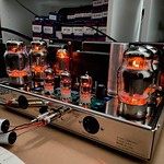
I ordered an ST-70 kit from Bob last week (via evilbay), and received it Monday. (Boredom and surfing audio forums and vendors in a hotel room while on a business trip can be costly! BTW, perfect timing on the shipping, Bob.) The quad of Winged C EL-34s from the Tube Store arrived Monday as well.
It's a very nicely put together kit - parts are bagged and labeled very clearly (I'm used to getting a bag of resistors and figuring out what's what myself), and everything appears to be of high quality.
The driver board was assembled almost completely Monday night - all that remains is to put the PIO coupling caps on, but first I want to dig through my mess and find the 3/4" clear shrink tubing that's buried somewhere to cover the bodies and insulate them.
Began assembling the chassis last night - tube sockets, binding posts, terminal strips & choke are in place. The hold up now is going to be finishing the transformers - hopefully I'll get time today to work on prettying them up a bit.
Thus far a very enjoyable build. (Not that I expected it would be anything else, of course...)
-Pat