
Ok, so I know it's not quite the Bruce Springsteen song title but seemed somehow apt.
After hitting a mid life crisis for the second time (First time I bought a fast Yamaha R6) I had an urge to build a valve audio amp. The idea had been brewing for quite a while since I had sold my Quad II mono blocks to pay for a holiday. At the outset let me say that at this stage I don't intend to make this a post describing how fantastic the finished amp sounds. This has been said many times in the past. (And it does...)
I did the normal searching and came up with two contenders. The first one was an amp with a name similar to an inventor of the light bulb and the second the Latino special. Emails were duly fired off and responses received. I reviewed the products, and the ease of making contact with the sellers and only really had one choice. Thanks Bob!! So PayPal did the deed and eventually I had a box of first class components arrive on my door step.
Now the fun began. I had a few requirements from the amplifier in that it must be capable of being used by my other half and it had to be as safe as practically possible. There would be times when it "might" get left on unattended. As we all know valves can fail, sometimes quite dramatically and to limit any further damage to transformers etc. we would need to switch off the power as soon as possible. So this got me thinking. The basic design of the ST-120 amp was born in the days of Teddy boys and health and safety hadn't been invented. Add to this that fact that the mains supply here in the UK is 230V, the original design only had one fuse, the case wasn't grounded, I felt a few modernisations were in order. No disrespect to the kit as supplied, the beauty of a kit is that it allows the constructor to install a degree of their own personality into the end product. If I had done anything to the Quad II's they would have lost all their "snake oil" and become worthless.
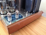
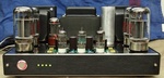
Unlike some of you that are reading this post I don't have a lot of room so the amp has to fit in with the other household items around it. This meant that it had to match the TV / Sky TV / CD in terms of appearance. It was therefore decided to move the inputs to the rear panel and cover the bias monitor socket to "modernise" the front look. I found that a 1U high 19" rack panel front was just the right height to fit both the front and rear panels. This was duly cut and screwed on. On the front I now have a push on/off button and four LEDs.
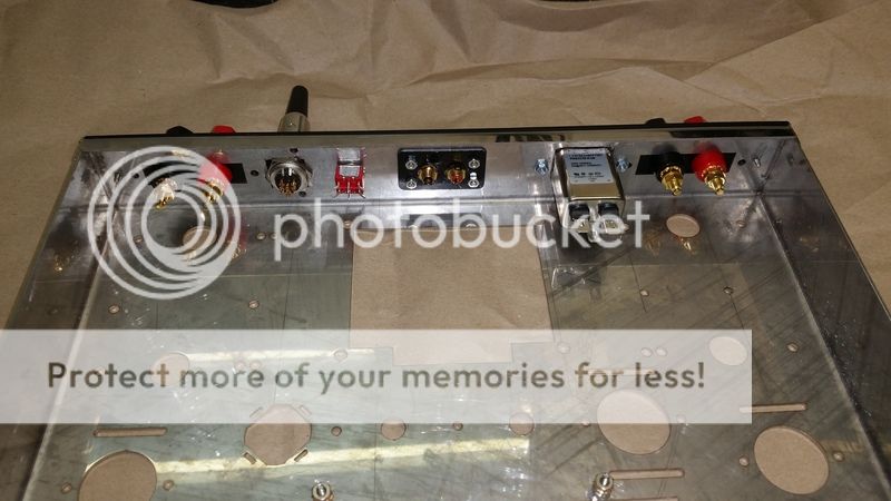
On the rear I wanted to mount a filtered mains input socket, a switch to change from 4 to 8 ohm speakers, audio inputs, speaker connections and finally a multipole socket from which I could remotely turn the amp on and off.
To allow for the remote switching, the front panel toggle switch, a delayed HT turn on and safety monitoring I employed a PIC processor (sorry did I swear in a valve section?). This PIC does the following:-
1 ) Allows for a toggle on/off function
2 ) Allows for remote on/off
3 ) Monitors the voltage across the individual cathode resistors.
4 ) Controls the mains power to the transformer
5 ) Provides a delayed HT switch on feature.
6 ) Drives each LED individually to indicate the correct standing current in each output valve. (fast flash too high, slow flash too low, on ok)
7 ) Monitors the -ve bias rail and will not enable HT unless this is present.
8 ) If excessive current is detected in any one of the output valves will shut off the amplifier.
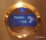
9 ) Special bias setting mode where the high/low tolerance of the LED indications is tightened to allow for precise setting to ~500mv as per spec.
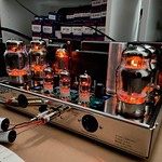
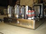
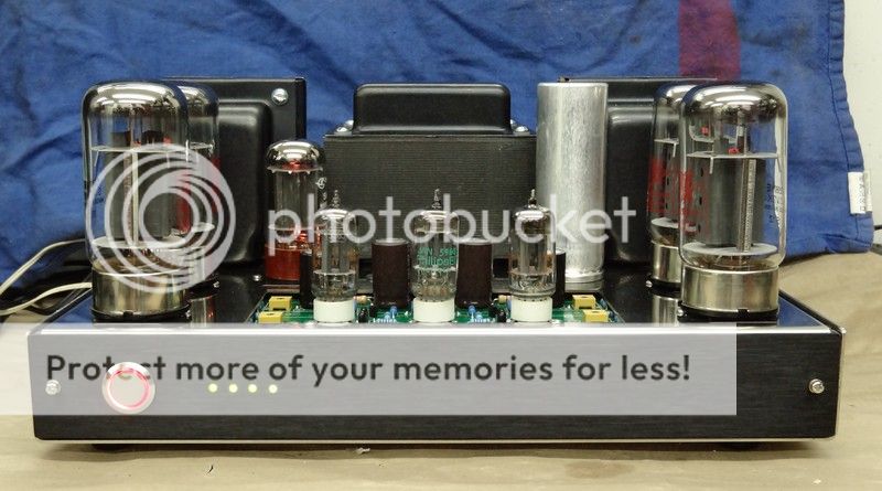
The basic circuit of the ST-120 is unaltered and follows Bob's instructions. I had to move the HT choke to create room for the control board. As an apprentice I learned the art of cable lacing. Now days everything is done by cable ties. I carefully laid out the audio wiring and laced them into a nice neat loom. I was a little worried that I might create an expensive audio oscillator by doing this but no fears. The amp is stable.
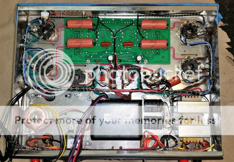
This picture shows the amp part way through construction. Almost ready to test out once I had joined up the mains and HT leads. So moving on I decided to incorporate fuses into the HT feed prior to the rectifier, and a further two fuses into the feed to the main transformer and also the low current standby toroidal one. A suitable place for these fuses was found to be on a panel above the triode/pentode switches.
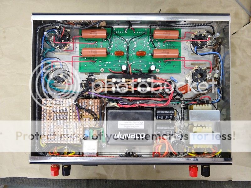
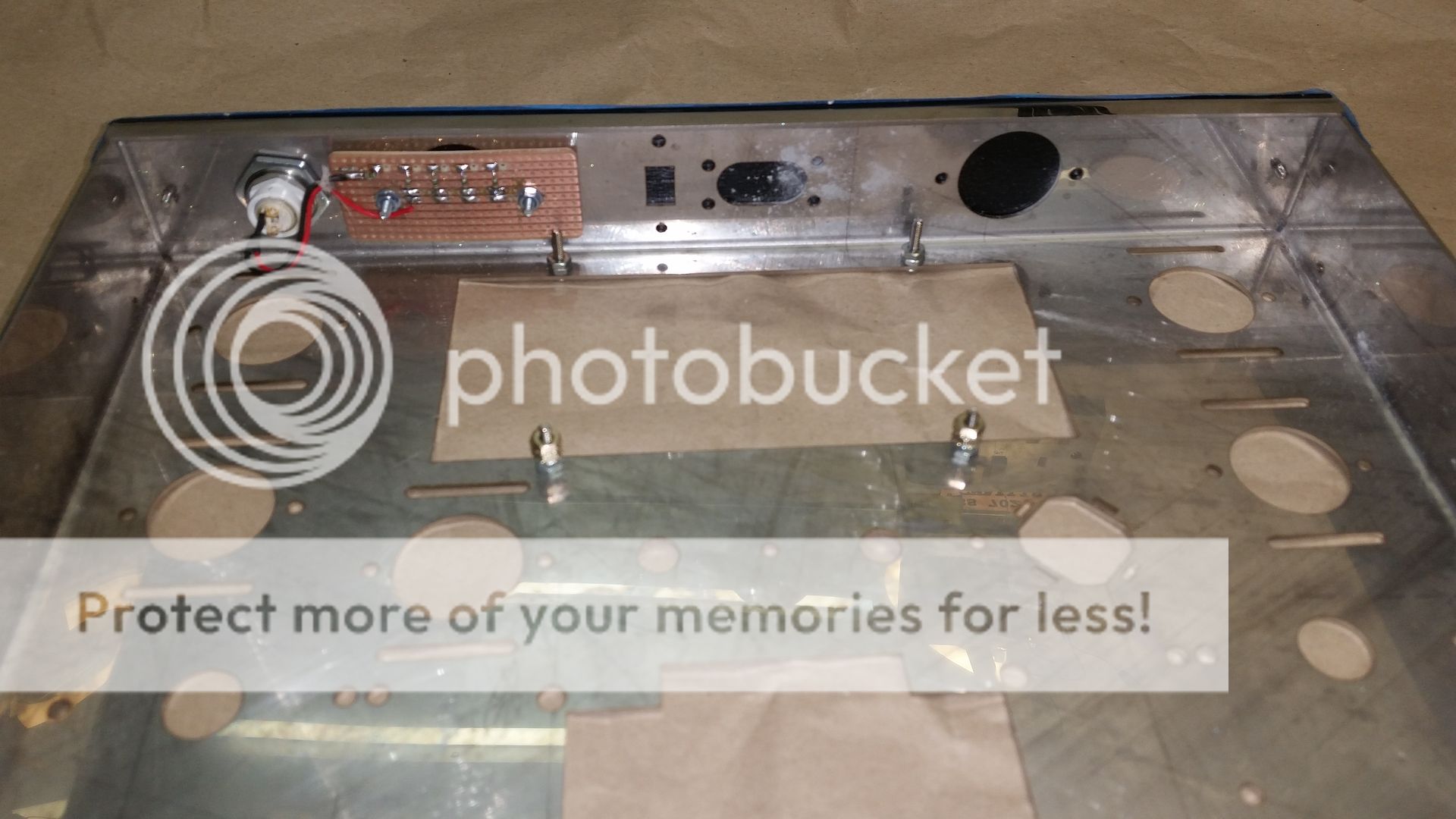
Finally a control board was built up on veroboard. I fully intend to make a proper PCB once the summer has passed and winter is here. The control board layout is a little messy but at least is can't be seen when fitted into place.

The firmware was written in C using the microchip XC16 free compiler.
From start to finish it took me a week and a half to complete on and off. I did have a little hiccup in that one of the 12AU7's didn't work out of the box. It must have suffered from an impaired vacuum as the getter was still silver but the heater did not light and it just got hot. Another one was ordered and it was here in a couple of days. Glad it wasn't one of the output valves!!
I suppose that I ought to stop typing and go and enjoy my ST-120 now. I'll review the amp and how it sounds another day.
Steve.

Three videos of the front panel LED's
After hitting a mid life crisis for the second time (First time I bought a fast Yamaha R6) I had an urge to build a valve audio amp. The idea had been brewing for quite a while since I had sold my Quad II mono blocks to pay for a holiday. At the outset let me say that at this stage I don't intend to make this a post describing how fantastic the finished amp sounds. This has been said many times in the past. (And it does...)

I did the normal searching and came up with two contenders. The first one was an amp with a name similar to an inventor of the light bulb and the second the Latino special. Emails were duly fired off and responses received. I reviewed the products, and the ease of making contact with the sellers and only really had one choice. Thanks Bob!! So PayPal did the deed and eventually I had a box of first class components arrive on my door step.
Now the fun began. I had a few requirements from the amplifier in that it must be capable of being used by my other half and it had to be as safe as practically possible. There would be times when it "might" get left on unattended. As we all know valves can fail, sometimes quite dramatically and to limit any further damage to transformers etc. we would need to switch off the power as soon as possible. So this got me thinking. The basic design of the ST-120 amp was born in the days of Teddy boys and health and safety hadn't been invented. Add to this that fact that the mains supply here in the UK is 230V, the original design only had one fuse, the case wasn't grounded, I felt a few modernisations were in order. No disrespect to the kit as supplied, the beauty of a kit is that it allows the constructor to install a degree of their own personality into the end product. If I had done anything to the Quad II's they would have lost all their "snake oil" and become worthless.
Unlike some of you that are reading this post I don't have a lot of room so the amp has to fit in with the other household items around it. This meant that it had to match the TV / Sky TV / CD in terms of appearance. It was therefore decided to move the inputs to the rear panel and cover the bias monitor socket to "modernise" the front look. I found that a 1U high 19" rack panel front was just the right height to fit both the front and rear panels. This was duly cut and screwed on. On the front I now have a push on/off button and four LEDs.

On the rear I wanted to mount a filtered mains input socket, a switch to change from 4 to 8 ohm speakers, audio inputs, speaker connections and finally a multipole socket from which I could remotely turn the amp on and off.

To allow for the remote switching, the front panel toggle switch, a delayed HT turn on and safety monitoring I employed a PIC processor (sorry did I swear in a valve section?). This PIC does the following:-
1 ) Allows for a toggle on/off function
2 ) Allows for remote on/off
3 ) Monitors the voltage across the individual cathode resistors.
4 ) Controls the mains power to the transformer
5 ) Provides a delayed HT switch on feature.
6 ) Drives each LED individually to indicate the correct standing current in each output valve. (fast flash too high, slow flash too low, on ok)
7 ) Monitors the -ve bias rail and will not enable HT unless this is present.
8 ) If excessive current is detected in any one of the output valves will shut off the amplifier.
9 ) Special bias setting mode where the high/low tolerance of the LED indications is tightened to allow for precise setting to ~500mv as per spec.
The basic circuit of the ST-120 is unaltered and follows Bob's instructions. I had to move the HT choke to create room for the control board. As an apprentice I learned the art of cable lacing. Now days everything is done by cable ties. I carefully laid out the audio wiring and laced them into a nice neat loom. I was a little worried that I might create an expensive audio oscillator by doing this but no fears. The amp is stable.

This picture shows the amp part way through construction. Almost ready to test out once I had joined up the mains and HT leads. So moving on I decided to incorporate fuses into the HT feed prior to the rectifier, and a further two fuses into the feed to the main transformer and also the low current standby toroidal one. A suitable place for these fuses was found to be on a panel above the triode/pentode switches.

Finally a control board was built up on veroboard. I fully intend to make a proper PCB once the summer has passed and winter is here. The control board layout is a little messy but at least is can't be seen when fitted into place.

The firmware was written in C using the microchip XC16 free compiler.
From start to finish it took me a week and a half to complete on and off. I did have a little hiccup in that one of the 12AU7's didn't work out of the box. It must have suffered from an impaired vacuum as the getter was still silver but the heater did not light and it just got hot. Another one was ordered and it was here in a couple of days. Glad it wasn't one of the output valves!!
I suppose that I ought to stop typing and go and enjoy my ST-120 now. I'll review the amp and how it sounds another day.
Steve.

Three videos of the front panel LED's