...so I'm hoping someone can explain this to me. 
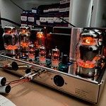
After posting my last query, I decided to just set the bias current to the -37v figure called for on the voltage check points page from Dynaco, and now the B+ voltages are good, and the power tubes appear to be biased within range as the plates show no overheating when viewed in a dark room...
...yet they're drawing around 70 milliamps of current when I interface a bias probe (same as taking a reading across a 1ohm resistor connected from pin 8 to ground) which I use when setting the bias current on a guitar amp.
In a guitar amp with +/- 440v on the plates, I'm pretty sure that an EL34 is going to be already starting to redplate pretty severely at this setting, yet they appear to be happy in this amp...
Yeah, I'm missing something...