The Dynaco Tube Audio Forum

Would you like to react to this message? Create an account in a few clicks or log in to continue.
The Dynaco Tube Audio Forum

Dedicated to the restoration and preservation of all original Dynaco tube audio equipment - Customer support for Tubes4hifi VTA tube amp and preamp kits and all Dynakitparts.com products


+2
Bally
Bob Latino
6 posters

    The new CCS VTA ST-70/ST-120 driver board (photos)

    Bob Latino
    Bob Latino
    Admin


    Posts : 3262
    Join date : 2008-11-26
    Location : Massachusetts

    The new CCS VTA ST-70/ST-120 driver board (photos) Empty The new CCS VTA ST-70/ST-120 driver board (photos)

    Post by Bob Latino Wed Oct 24, 2012 9:55 am

    As of April 1, 2012 Tubes4hifi (Roy) introduced the new CCS version of the VTA ST-70 driver board ... Photos of both boards and some differences are listed below ...

    The circuit of both boards is basically the same with a few minor differences ...

    1. The resistor set is different and the board is now set up for the lower gain 12AU7 or 12BH7 driver tubes instead of 12AT7 medium gain driver tubes. The newer board has somewhat lower gain than the older board .. This is a good thing especially if you have very efficient (93 dB or higher) speakers.

    2. The phase splitter now uses "CCS" a Constant Current Source in the tail of the phase splitter. In the older board there was an AC balance control for each channel which the user would set in the center of its rotation. Set this way and using a matched pair of output tubes, the AC balance was near optimum. The newer board now uses a small integrated circuit which provides a local feedback loop that feeds an error correction signal to the tail of the phase splitter. The signal fed is inverted so any deviation is cancelled. This type of phase splitter is more accurate in maintaining AC balance on the phase splitter section of the driver board. This CCS phase splitter was created by (the late) Fred Nachbaur in 2002. A more technical explanation by Fred is here > CCS phase splitter - Fred Nachbaur

    3. In the older board the four bias pots worked "counterintuitive". Turning the pots to the right or clockwise REDUCED the bias voltage and turning the bias pots to the left or counterclockwise INCREASED the bias voltage. The newer board has the the bias pots set up so that clockwise rotation increases bias voltage and counterclockwise rotation decreases bias voltage.

    4. On the new board two filament jumpers are now used to send the 6.3 volt AC filament voltage from V3 to V2 to provide filament voltage for the center voltage amplifier tube. Also, the driver tubes are now designated V1, V2 and V3 from left to right which is slightly different from the older board.

    As a side note I have found this board to be very flexible in regards to what LOWER GAIN driver tubes may be used. I have used 12AU7, 12BH7, 5963, 5814 and 6189 driver tubes and found that they ALL work well in this newest iteration of the VTA driver board.

    Bob

    Older VTA driver board
    The new CCS VTA ST-70/ST-120 driver board (photos) VTAdriverboardNEW_sideways-2

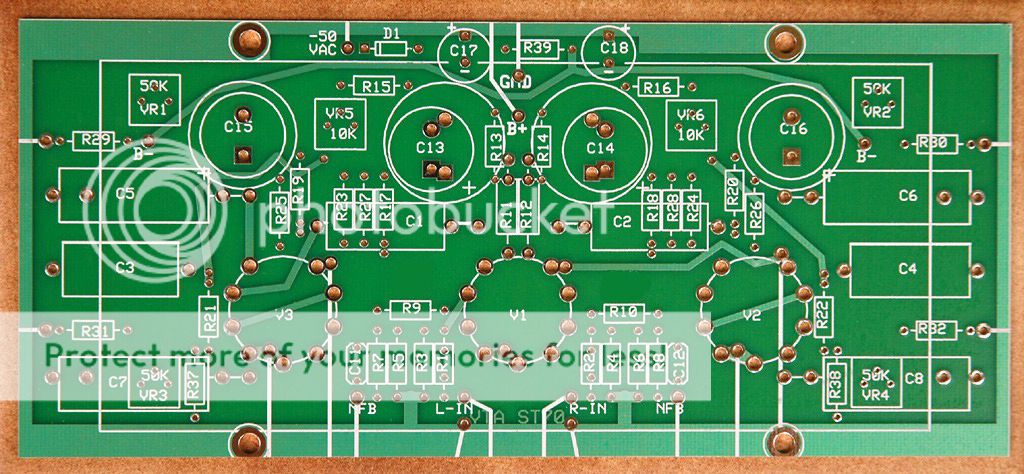
    Newer VTA driver board
    The new CCS VTA ST-70/ST-120 driver board (photos) CCSdriverboard


    Last edited by Bob Latino on Thu Oct 25, 2012 6:03 pm; edited 1 time in total
    avatar
    Bally


    Posts : 25
    Join date : 2010-05-18

    The new CCS VTA ST-70/ST-120 driver board (photos) Empty Re: The new CCS VTA ST-70/ST-120 driver board (photos)

    Post by Bally Wed Oct 24, 2012 11:58 am

    Hmmmm....now why would he do that on April 1st?????
    Roy Mottram
    Roy Mottram
    Admin


    Posts : 1839
    Join date : 2008-11-30

    The new CCS VTA ST-70/ST-120 driver board (photos) Empty Re: The new CCS VTA ST-70/ST-120 driver board (photos)

    Post by Roy Mottram Wed Oct 24, 2012 4:11 pm

    actually I started selling these new boards in February of 2012 . . . . Bob had leftovers of the older version until April
    avatar
    tomlang


    Posts : 36
    Join date : 2009-08-12

    The new CCS VTA ST-70/ST-120 driver board (photos) Empty Re: The new CCS VTA ST-70/ST-120 driver board (photos)

    Post by tomlang Thu Oct 25, 2012 9:24 am

    What is the solid state device used for the CCS? If this is proprietary I apologize for asking, thanks.

    avatar
    Bally


    Posts : 25
    Join date : 2010-05-18

    The new CCS VTA ST-70/ST-120 driver board (photos) Empty Re: The new CCS VTA ST-70/ST-120 driver board (photos)

    Post by Bally Thu Oct 25, 2012 9:25 am

    Thanks for the clarification Roy.....Of course I was being a little tongue and cheek here.
    I have one of the older designed boards and since my ST70 build is still in progress - going
    six years now...no kidding - when its finally complete - maybe another year or so I have to remember
    the proper orientation for bias adjustment. Otherwise I'll be scratching my head wondering why
    would Roy use a pot that work "backwards".
    Bob Latino
    Bob Latino
    Admin


    Posts : 3262
    Join date : 2008-11-26
    Location : Massachusetts

    The new CCS VTA ST-70/ST-120 driver board (photos) Empty Re: The new CCS VTA ST-70/ST-120 driver board (photos)

    Post by Bob Latino Thu Oct 25, 2012 10:10 am

    tomlang wrote:What is the solid state device used for the CCS? If this is proprietary I apologize for asking, thanks.


    Hi Tom,

    No - It's not a proprietary device ... It is an off the shelf Texas Instrument LM334 small integrated circuit.

    Some users may cringe at a "solid state device" on a tube amp but the IC is not in the signal path. It is just used for current balance at a critical point in the phase splitter part of the driver circuit. The technical specs for the LM334 are on a spec sheet at the link below.

    LM334 technical sheet

    Bob
    avatar
    dunwichamps


    Posts : 36
    Join date : 2011-10-20

    The new CCS VTA ST-70/ST-120 driver board (photos) Empty Re: The new CCS VTA ST-70/ST-120 driver board (photos)

    Post by dunwichamps Wed Oct 31, 2012 2:28 pm

    So to add a little bit of info for folks. When designing a long tail phase inverter (LTPI) there is usually a trade off between output swing and output balance. Swing refers to the maximum output amplitude before clipping and the balance is how closely do the 2 output waveforms of the phase inverter match in terms of amplitude. So the ideal balance would be identical in amplitude but exactly 180 degrees out of phase. However in real life there is no perfect balance between the outputs resulting in harmonic distortion in the power amp.

    The trade off happens when you want to get more output swing and this causes a greater degree of inbalance in the outputs. This is because the general method of increase output swing is to decrease the tail resistance of the LTPI. To improve balance you can increase the tail resistance and or inbalance the LTPI plate resistors to adjust the gain of each half of the LTPI

    the more superior method is to use a CCS as the tail resistance in the LTPI which allows for much better balance and more output swing using as Bob said a local feedback loop in the tail of the LTPI. Hopefully this is clear, and call me out of this is wrong.
    Roy Mottram
    Roy Mottram
    Admin


    Posts : 1839
    Join date : 2008-11-30

    The new CCS VTA ST-70/ST-120 driver board (photos) Empty Re: The new CCS VTA ST-70/ST-120 driver board (photos)

    Post by Roy Mottram Wed Oct 31, 2012 4:18 pm

    yes, all true, and the reason I finally decided to go ahead with the CCS chip, is because it offer superior performance to just using the usual tail resistor which was previously 12K as an optimum compromise. The CCS chip give near infinite impedance, thus offering a higher voltage swing and automatically compensating for the signal and giving perfect balance (amplitude and phase) with zero adjustment needed, and lower distortion than using a simple resistor.
    avatar
    dunwichamps


    Posts : 36
    Join date : 2011-10-20

    The new CCS VTA ST-70/ST-120 driver board (photos) Empty Re: The new CCS VTA ST-70/ST-120 driver board (photos)

    Post by dunwichamps Wed Oct 31, 2012 4:26 pm

    right on. I have done simulations of 12au7 LTPIs using just 1 BJT in a feedback loop with a tail resistor and its a significant improvement in the balance vs swing design standpoint compared to just a tail resistor. I will probably be building 1 of these kits soon, in 2013 or so, and i dig the addition of a CCS.
    mrconclusion
    mrconclusion


    Posts : 15
    Join date : 2012-10-18

    The new CCS VTA ST-70/ST-120 driver board (photos) Empty Re: The new CCS VTA ST-70/ST-120 driver board (photos)

    Post by mrconclusion Fri Nov 02, 2012 9:49 pm

    I can't contribute much to the technical discussion, but I have two VTA ST-70's sitting right next to each other. One has the previous driver board and the other has the new CCS board. So, I'm fortunate to have a chance to test the two driver boards with the same inputs, preamp, loudspeakers, and even moving the same power tubes back and forth. I only wish I had more 12AU7-types to test.

    I always liked my first ST-70, but the new driver board is a clear improvement. The combination of lower gain and better phase splitting definitely works! The new board is quieter - at zero attenuation with no signal tube hiss and 60hz hum are absent or nearly nonexistent. I believe there is more clarity (lack of distortion?) especially on very clean vinyl and pure recordings. The new board still gives the same sense of effortless dynamics and has no problem showing off the differences between EL34's, KT66's, and KT88's without making any of them sound bad.

    Sorry I can't describe the listening experience in better detail, but consider this a thumbs-up to the CCS driver board after the most controlled comparison I can perform.

    Sponsored content


    The new CCS VTA ST-70/ST-120 driver board (photos) Empty Re: The new CCS VTA ST-70/ST-120 driver board (photos)

    Post by Sponsored content


      Current date/time is Fri Apr 26, 2024 11:54 am