The Dynaco Tube Audio Forum

Dedicated to the restoration and preservation of all original Dynaco tube audio equipment - Customer support for Dynaco VTA tube amp kits, all Tubes4hifi.com products and all Dynakitparts.com products

    Board layouts for the PC-5 line stage and PC-6 phono board on the PAS preamps - photos ...

    Share

    Bob Latino
    Admin

    Posts: 1541
    Join date: 2008-11-26
    Location: Massachusetts

    Board layouts for the PC-5 line stage and PC-6 phono board on the PAS preamps - photos ...

    Post by Bob Latino on Sat Dec 05, 2009 7:51 am

    Roy Mottram of tubes4hifi was kind enough to let me post his board layouts for the PC-5 line stage and PC-6 phono board as found on the PAS-2 and PAS-3 preamps. Dynaco never listed the parts on these two boards in their assembly manual. When you got your PAS-2 or PAS-3 kit the boards were already preassembled.

    Bob

    PC-5 board


    PC-6 board


    tubes4hifi
    Admin

    Posts: 737
    Join date: 2008-11-30

    resistors on PAS3 PCBs

    Post by tubes4hifi on Wed Dec 15, 2010 1:23 pm

    I've got a pair of PCBs in front of me with the schematics. The listing for the 100K 1w is incorrect,
    on the schematic of the PC-6 phono board the 150K is marked as 1w. The actual boards I have in front of me
    has a 1/2 watt resistor on it, it's 40 years old, doesn't even look like it ever got warm.
    Using the voltage chart from the PAS3 manual, that resistor has 95v across 150K equals .63ma and
    that is .06 watts. The one resistor with the most power across it is the 100K plate resistor on PC-5 line amp.
    It has 130v across 100K for 1.3ma and that is .169 watts, about 1/3 of 1/2 watt rating.
    On the actual boards I have in front of me that 100K is a 1w resistor even though the schematic doesn't
    spec that. It is an original part. None of the cathode resistors use more than .06w - See updated board layouts below ...

    Roy @ www.tubes4hifi.com


    rhollingsworth

    Posts: 1
    Join date: 2012-10-16

    Re: Board layouts for the PC-5 line stage and PC-6 phono board on the PAS preamps - photos ...

    Post by rhollingsworth on Tue Oct 16, 2012 12:01 pm

    The caps 1500 pf and .004 uF... what were they for anyway? The circuit can do without them? Thanks.

    turbodan

    Posts: 5
    Join date: 2012-07-06

    Re: Board layouts for the PC-5 line stage and PC-6 phono board on the PAS preamps - photos ...

    Post by turbodan on Thu Nov 01, 2012 9:00 pm

    Can anyone provide some insight as to why in the PC5 diagram provided by tubes4hifi the 7500pF caps are substituted with 6800pF replacements? It seems like this would have a negative effect on treble response....

    tubes4hifi
    Admin

    Posts: 737
    Join date: 2008-11-30

    Re: Board layouts for the PC-5 line stage and PC-6 phono board on the PAS preamps - photos ...

    Post by tubes4hifi on Sat Nov 03, 2012 6:44 pm

    in reply to the last two posts, the .002 cap connected to eyelet 4 is part of the treble tone circuit.
    as for replacing the 7500pf with 6800pf in the bass section, two reasons I do this, one, try finding a 7500pf cap . . .
    2nd, both the treble controls and the bass controls have WAY too much gain in a stock PAS, so subbing a 6800pf for a 7500pf
    is a fairly minor change and might only give you 12db (that's 4X !!) of boost/cut instead of 15db.

    thinker1920

    Posts: 17
    Join date: 2013-04-04
    Age: 24
    Location: Binghamton, NY

    Re: Board layouts for the PC-5 line stage and PC-6 phono board on the PAS preamps - photos ...

    Post by thinker1920 on Thu Apr 04, 2013 11:14 pm

    Just wondering what wattage the resistors are suppose to be and what voltage the caps are suppose to be? thanks

    tubes4hifi
    Admin

    Posts: 737
    Join date: 2008-11-30

    Re: Board layouts for the PC-5 line stage and PC-6 phono board on the PAS preamps - photos ...

    Post by tubes4hifi on Fri Apr 05, 2013 1:13 pm

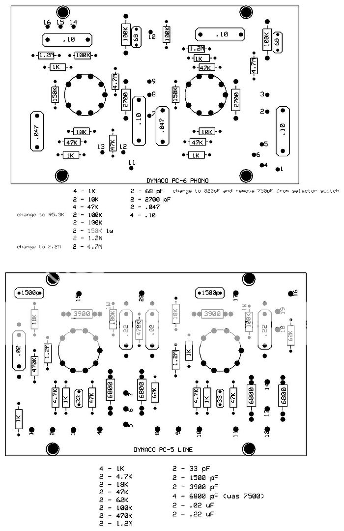
    look at the info at the top of this page - all resistors are half watt except one is marked one watt.
    Most capacitors should be rated at 400vdc (you can always check the schematics to be sure of anything).
    Here is a copy of the original PAS schematic that I've labeled so you can tell what is what,
    then two much better re-drawings of the two PCB schematics.
    In an original PAS preamp, PC6 eyelet 4 and eyelet 11 have two separate connections to chassis ground,
    when I service these preamps I cut both ground wires out and run a single ground connection to eyelet 10,
    and then connect eyelet 4 and eyelt 11 together with a wire, as shown on the bottom schematic.


    Last edited by tubes4hifi on Sat Apr 06, 2013 6:27 pm; edited 2 times in total

    thinker1920

    Posts: 17
    Join date: 2013-04-04
    Age: 24
    Location: Binghamton, NY

    Re: Board layouts for the PC-5 line stage and PC-6 phono board on the PAS preamps - photos ...

    Post by thinker1920 on Fri Apr 05, 2013 1:54 pm

    Thanks, I find the original diagrams confusing, I didn't see where they labeled the voltage rating of the board capacitors, I've been trying to figure out what the voltage should be at the last stage of the filter to the boards.


    Last edited by thinker1920 on Fri Apr 05, 2013 1:55 pm; edited 1 time in total (Reason for editing : typo)

      Current date/time is Tue Jun 18, 2013 1:51 am