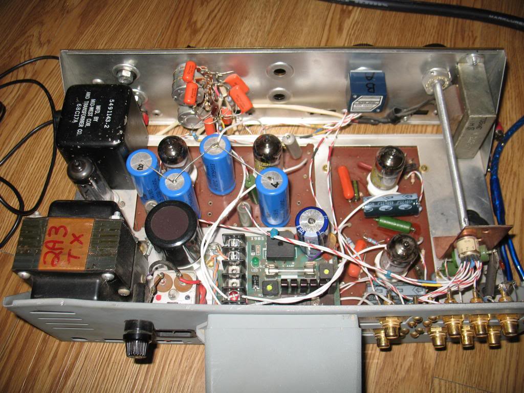
 by DarthBubba Mon Apr 08, 2013 4:27 pm
thinker1920 wrote:.1 uF.... also wanted to ask about the differences between the diagram in the sticky on this forum and the pdf you recommended, which one should I follow? the pdf says to bypass two of the .1 uF caps and the sticky still has them in place, the pdf says 2.0 meg resistor, the sticky a 2.2 meg. Sorry to be a pain, and thank you for your help.
Oh, and it gets much worse my friend!
Depending on whom you read, some of the modders say to replace the plain-wire-bypassed cap with a bigger cap!
My take is: the fewer parts in the signal path, the better. So, measure the voltage at eyelet 3 (R-Ch) and eyelet 9 (L-Ch). If there's no DC voltage there on your DVM's most sensitive level (and DO start at it's highest voltage range then step down, please

) I'd say just jumper it out. If there IS voltage DC voltage there, keep the cap. The answer about what to do with your spare Russian PIOs also is answered - put the 500v one between each eyelet and the tube that "feeds" it; the other between eyelets 3 & 5 (R-Ch) and between eyelets 7 & 9 (L-Ch). BTW, if you have the Black Cat capacitors that came with the board originally - you may want to save you Russian PIOs for something else. The Black Cat branded caps are PIO also, just American made.
2.2meg vs 2meg is inconsequential. Use the quietest ones, or the two that match the best.
I also differ with the usual RIAA mod instructions at this step: Replace the 68pF cap with the 750pF cap you removed from the selector switch. 750pF is closer to the correct value than 820pF. The math says so. So does E.E. Professor Stanley Lipschitz, AES member who presented the corrected RIAA network at the AES convention in 1976, or so. People use 820 because 750pF isn't a standard value.


 The word frankenstein comes to mind!

 Be the better friend.


