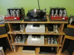
I have a mark III with vta pcb that has blown both 10 amp bias resistors. when I opened the chassis up I noticed that the connections to pins 7 and 8 on the socket that has the green wires from the transformer were very close to touching. what would be the outcome if they did indeed touch while the amp was running. what else could be damaged besides the bias resistors.
3 posters
bias resistors blown

Bob Latino- Admin
- Posts : 3276
Join date : 2008-11-26
Location : Massachusetts
- Post n°2
 Re: bias resistors blown
Pin #7 carries one leg of the filament current and pin #8 is where the bias resistor is connected. If those two pins do touch OR are close enough so that you could get an arc from one pin to the other, you most likely will blow the fuse. You could possibly damage that tube also. Those resistors are 10 OHMS @ 1 or 2 watts. They are not 10 amp resistors.
Bend both pins 7 and 8 back a little away from the center of the tube socket to get the pins away from each other and then get two 10 ohm 1 watt resistors from your local Radio Shack. They come in two packs. Part # 271-151
Bob
Bend both pins 7 and 8 back a little away from the center of the tube socket to get the pins away from each other and then get two 10 ohm 1 watt resistors from your local Radio Shack. They come in two packs. Part # 271-151
Bob

wedg714- Posts : 74
Join date : 2011-11-23
- Post n°3
 Re: bias resistors blown
I replaced the resistors and everything seemed fine but after a couple hours of use the tube started glowing bright red and the bias shoots way up. what else could have been damaged?

Bob Latino- Admin
- Posts : 3276
Join date : 2008-11-26
Location : Massachusetts
- Post n°4
 Re: bias resistors blown
I am thinking that the TUBE itself could now be bad ? Try replacing that tube and see if the new tube biases up properly and will not "red plate" (glow brightly or form a red spot on the plate of the output tube) after being on for a few hours ..
Bob
Bob

wedg714- Posts : 74
Join date : 2011-11-23
- Post n°5
 Re: bias resistors blown
already did that. new tubes, new resistors. after a couple of hours the same tube glows bright red and the bias shoots way up

Bob Latino- Admin
- Posts : 3276
Join date : 2008-11-26
Location : Massachusetts
- Post n°6
 Re: bias resistors blown
Ok - Try replacing the coupling capacitor on the driver board for that tube. That cap could be passing DC after it heats up ..
Also > Check the negative DC voltage on both pins 5 and 6. With the bias set properly, it should be in the range of -45 to -60 volts DC. If this bias voltage is way off, there could be an issue with the bias system ..
Bob
Also > Check the negative DC voltage on both pins 5 and 6. With the bias set properly, it should be in the range of -45 to -60 volts DC. If this bias voltage is way off, there could be an issue with the bias system ..
Bob

wedg714- Posts : 74
Join date : 2011-11-23
- Post n°7
 Re: bias resistors blown
what number would the caps be on the pcb? c17 and c18?

Roy Mottram- Admin
- Posts : 1839
Join date : 2008-11-30
- Post n°8
 Re: bias resistors blown
the bias caps are C17 and C18, 100uF 100v, note that the positive lead should go to ground, as these filter the NEGATIVE bias supply voltage.
Also, the output coupling caps that Bob referred to are C6 and C8. Make sure you have good solder connections on the socket where the tube keeps going bad.
In all cases, refer to your documentation (or ask for a new copy) and it seems maybe you didn't mount the board using the spacers that are included,
that' keeps anything around the edges from touching the chassis.
