The Dynaco Tube Audio Forum

Would you like to react to this message? Create an account in a few clicks or log in to continue.
The Dynaco Tube Audio Forum

Dedicated to the restoration and preservation of all original Dynaco tube audio equipment - Customer support for Tubes4hifi VTA tube amp and preamp kits and all Dynakitparts.com products


+7
jrubin
Bob Latino
DynakitParts
GP49
mazeeff
sKiZo
peterh
11 posters

    Barn find ST70

    jrubin
    jrubin


    Posts : 85
    Join date : 2015-08-28

    Barn find ST70 Empty Barn find ST70

    Post by jrubin Sat Oct 03, 2015 11:39 pm

    Im working on a barn find - video coming shortly. Im trying to keep the unit stock with the exception of some 7199 converter sockets. I have a nice modded ST70 for regular use, this one landed in my lap and will be used for testing and understanding to compliment my new Hantek 5072P


    A few questions however.......

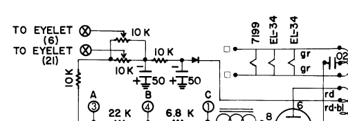
    The two 50MFD caps on the power supply. Rated at 75V. These need to be replaced. One has an ESR off the charts and measures in at 11MFD. What do you feel a good replacement should be?
    Should I stay at 50MFD and 75VDC rating or could I benefit from a higher capacitance?

    The output transformer inductance readings show the following. The right jack seems to have higher inductance. Does this reading look ok?

    LEFT
    16 OHM - 70mh
    8 OHM - 28.8mh
    4 OHM - 14mh

    RIGHT
    16 OHM - 85mh
    8 OHM - 33mh
    4 OHM - 17mh


    The RF choke measured 65 OHMS at the multi capacitor can and .87H.. I cant find the specification for this

    Whats a good way to measure the selenium rectifier. I generally replace them, but want to keep it in this unit.


    If you are still reading this... does anyone have the NO-LOAD voltage readings for the power transformer... That is to say. what it reads with all tubes removed.


    Thanks much, in advance


    Jordan

    avatar
    Guest
    Guest


    Barn find ST70 Empty Re: Barn find ST70

    Post by Guest Sun Oct 04, 2015 12:12 am

    .


    Last edited by PeterCapo on Thu Dec 03, 2020 10:03 pm; edited 1 time in total
    peterh
    peterh


    Posts : 1833
    Join date : 2012-12-25
    Location : gothenburg, sweden

    Barn find ST70 Empty Re: Barn find ST70

    Post by peterh Sun Oct 04, 2015 2:45 am

    I would advice NOT to increase the capacitance of the bias caps. Reason is that it is importent
    that bias is established before B+ on every possible sequence of events.
    The existing cap ( 50uF) is more then sufficient. 100V as petercapo suggests , is a good advice.

    I would also recommend to replace the selenium diode. It will fail, just wait.
    If you want to keep it for display, at least parallel it with a Si diode ( and adjust the resistor chain)
    avatar
    Guest
    Guest


    Barn find ST70 Empty Re: Barn find ST70

    Post by Guest Sun Oct 04, 2015 1:54 pm

    .


    Last edited by PeterCapo on Thu Dec 03, 2020 10:03 pm; edited 1 time in total
    peterh
    peterh


    Posts : 1833
    Join date : 2012-12-25
    Location : gothenburg, sweden

    Barn find ST70 Empty Re: Barn find ST70

    Post by peterh Sun Oct 04, 2015 2:08 pm

    PeterCapo wrote:
    peterh wrote:I would advice NOT to increase the capacitance of the bias caps. Reason is that it is importent
    that bias is established before B+ on every possible sequence of events.

    Can you say more about this, please?

    If the cathodes are hot and B+ comes before bias then the tubes might be overloaded and
    flashover. This will destrouy the output tubes if unlucky.
    Thus and measure must be taken to make shure bias is at correct level before B+
    jrubin
    jrubin


    Posts : 85
    Join date : 2015-08-28

    Barn find ST70 Empty Re: Barn find ST70

    Post by jrubin Sun Oct 04, 2015 2:40 pm

    Heres a video of some of the work ive done thus far.......


    avatar
    Guest
    Guest


    Barn find ST70 Empty Re: Barn find ST70

    Post by Guest Sun Oct 04, 2015 2:46 pm

    with any restoration, I feel, always start at the power supply, especially the caps and older resistors, then work your way to and through the rest of the circuit, again giving good attention to caps, solder joints, wires etc..
    Once up and running properly, then maybe fine tune it with better coupling caps, maybe some good quality film resistors and tube rolling as well.
    avatar
    Guest
    Guest


    Barn find ST70 Empty Re: Barn find ST70

    Post by Guest Sun Oct 04, 2015 2:57 pm

    .


    Last edited by PeterCapo on Thu Dec 03, 2020 10:04 pm; edited 1 time in total
    jrubin
    jrubin


    Posts : 85
    Join date : 2015-08-28

    Barn find ST70 Empty Re: Barn find ST70

    Post by jrubin Sun Oct 04, 2015 3:20 pm

    Unfortunately the 7199's (at least) one of them cannot be tested in curcuit as it has a short.


    Im going to load in the EL34's and turn up the voltage to see what I get for heater and grid bias
    peterh
    peterh


    Posts : 1833
    Join date : 2012-12-25
    Location : gothenburg, sweden

    Barn find ST70 Empty Re: Barn find ST70

    Post by peterh Sun Oct 04, 2015 3:40 pm

    PeterCapo wrote:
    peterh wrote:
    PeterCapo wrote:
    peterh wrote:I would advice NOT to increase the capacitance of the bias caps. Reason is that it is importent
    that bias is established before B+ on every possible sequence of events.

    Can you say more about this, please?

    If the cathodes are hot and B+ comes before bias then the tubes might be overloaded and
    flashover. This will destrouy the output tubes if unlucky.
    Thus and measure must be taken to make shure bias is at correct level before B+

    I do remember having read some things along the way about not making the bias capacitors too large.  This is an interesting possibility.

    But, I’m wondering how a somewhat larger value bias capacitor might make it more likely that there would be a runaway bias condition, or some sort of flash-over, for the power tubes.  

    Do you mean that the initial charging cycle for, say, a 150uF vs. 50uf bias capacitor would be sufficiently longer such that the power tubes could have a run-away condition?  Seems like the charging cycle of even a larger capacitor would be quite short compared with the time it takes for the filaments to heat up, wouldn’t you say?  Or, is there something else I am missing?

    Thank you.
    Peter
    In normal start the bias would come up even with very large caps. But, power glitches
    might unload both B+ and bias, but as cathodes are still hot the b+ might come up
    faster.

    And as 50uF is more then needed , why increase it ??
    avatar
    Guest
    Guest


    Barn find ST70 Empty Re: Barn find ST70

    Post by Guest Sun Oct 04, 2015 3:55 pm

    .


    Last edited by PeterCapo on Thu Dec 03, 2020 10:05 pm; edited 4 times in total (Reason for editing : Clarification.)
    sKiZo
    sKiZo


    Posts : 1530
    Join date : 2013-04-01
    Location : Michigan USA

    Barn find ST70 Empty Re: Barn find ST70

    Post by sKiZo Sun Oct 04, 2015 4:07 pm

    All the points about power fluctuations should be moot if you're using a circuit interrupter with a manual reset? Any brown out strong enough to cause problems should trip that.

    Theoretically, of course.
    avatar
    Guest
    Guest


    Barn find ST70 Empty Re: Barn find ST70

    Post by Guest Sun Oct 04, 2015 4:17 pm

    .


    Last edited by PeterCapo on Thu Dec 03, 2020 10:05 pm; edited 1 time in total
    peterh
    peterh


    Posts : 1833
    Join date : 2012-12-25
    Location : gothenburg, sweden

    Barn find ST70 Empty Re: Barn find ST70

    Post by peterh Sun Oct 04, 2015 4:17 pm

    I would'nt increase the bias cap. But thats me. YMMV.
    Enough said.
    jrubin
    jrubin


    Posts : 85
    Join date : 2015-08-28

    Barn find ST70 Empty Re: Barn find ST70

    Post by jrubin Sun Oct 04, 2015 4:44 pm

    I ve reached an issue today. while setting up the grid bias I have no voltage on the 1.56 terminals nor pins 1 or 6 on the EL34's


    Changes to the trim pots cause a change in voltage to el34 pins 5 and 6 which show about 33 volts.

    Also I was able to test the selenium rectifier good which matched the manual at top 65vDC and bottom 50VAC


    jrubin
    jrubin


    Posts : 85
    Join date : 2015-08-28

    Barn find ST70 Empty Re: Barn find ST70

    Post by jrubin Sun Oct 04, 2015 5:13 pm

    Wait a minute.....

    The manual says to set up the bias before putting in the rectifier tube.  Without the rectifier tube there is no high tension DC.  Therefore no current flow... so there would be no way to set up the bias.


    Just to be sure I pulled the rectifier from my other ST70 and sure enough, no readings on the 1.56 terminals without the rectifier.   Why would they write that in the manual?


    EDIT:   Ahhh ok , it only says to center the pots without the rectifier..... not that you would get a reading... only after installation would the reading be present when current flows


    I find it interesting that I cant find a 50uf 75v or 100v capacitor on any of the dyna parts websites
    avatar
    Guest
    Guest


    Barn find ST70 Empty Re: Barn find ST70

    Post by Guest Sun Oct 04, 2015 6:33 pm

    .


    Last edited by PeterCapo on Thu Dec 03, 2020 10:06 pm; edited 1 time in total
    Bob Latino
    Bob Latino
    Admin


    Posts : 3263
    Join date : 2008-11-26
    Location : Massachusetts

    Barn find ST70 Empty Re: Barn find ST70

    Post by Bob Latino Sun Oct 04, 2015 7:06 pm

    You can use the caps at the link below . It is Nichicon 100 uF @ 100 volt cap. Two of these are used as the bias caps in all the VTA amp kits.

    Nichicon 100 uF @ 100 volt caps

    Bob
    jrubin
    jrubin


    Posts : 85
    Join date : 2015-08-28

    Barn find ST70 Empty Re: Barn find ST70

    Post by jrubin Sun Oct 04, 2015 8:13 pm

    Hello Bob,


    So what you are saying is to use 100uf vice the original 50uf ones in the amp?
    Bob Latino
    Bob Latino
    Admin


    Posts : 3263
    Join date : 2008-11-26
    Location : Massachusetts

    Barn find ST70 Empty Re: Barn find ST70

    Post by Bob Latino Sun Oct 04, 2015 8:33 pm

    jrubin wrote:Hello Bob,


    So what you are saying is to use 100uf vice the original 50uf ones in the amp?

    Yes - It won't really make any difference. Dynaco use 50 uF caps back then because electrolytic caps were more expensive in relation to the total cost of the amp. Two 50 uF caps are probably minimum capacitance for DC storage for the amp's bias system. Modern electrolytic caps are physically smaller for their capacitance and a lot less costly in relation to the total cost of the amp. Those Nichicon 100 uF @ 100 volt caps are smaller than Dynaco's original 50 uF caps. They are also better made, more reliable and will last longer than Dynaco's two original 50 uF caps. That statement is not meant to knock Dynaco. It is not fair to compare what is available today to what was available 50+ years ago. Dynaco did the best they could to sell a decent tube amp to the masses. A lot of people back then could not afford McIntosh and Harmon Kardon gear. In 1959 the Dynaco ST-70 kit sold for $99 with a complete tube set plus a tube cage. It is hard to believe that they could sell the ST-70 at that price but they did and sold 350,000+ ST-70 amps ..

    Bob
    jrubin
    jrubin


    Posts : 85
    Join date : 2015-08-28

    Barn find ST70 Empty Re: Barn find ST70

    Post by jrubin Sun Oct 04, 2015 9:06 pm

    Is this an electrolytic cap... i see that its polarized....
    jrubin
    jrubin


    Posts : 85
    Join date : 2015-08-28

    Barn find ST70 Empty Re: Barn find ST70

    Post by jrubin Sun Oct 04, 2015 10:07 pm

    Part II posted..... I should have realized that without the rectifier there would be no current flow.....


    avatar
    mazeeff


    Posts : 155
    Join date : 2014-01-06
    Age : 69
    Location : Grand Rapids, Michigan, USA

    Barn find ST70 Empty Re: Barn find ST70

    Post by mazeeff Mon Oct 05, 2015 7:17 am

    Very nice video! If I read the date codes on the bias pots correctly, this amp was kitted in 1963. Both pots have similar date codes, which supports 1963. I like the patina on the amp. Any idea how long it sat idol?

    Mike
    jrubin
    jrubin


    Posts : 85
    Join date : 2015-08-28

    Barn find ST70 Empty Re: Barn find ST70

    Post by jrubin Mon Oct 05, 2015 5:55 pm

    I am told 40 years.... Mostly as a display piece and possibly in storage too
    jrubin
    jrubin


    Posts : 85
    Join date : 2015-08-28

    Barn find ST70 Empty Re: Barn find ST70

    Post by jrubin Mon Oct 05, 2015 8:26 pm

    So Ive purchased some go-no-further parts for the unit.

    2x 100uf 450v caps

    20/20/20/30 cap -   I figured, if im gonna stay original.....


    Since Im going no further till the parts arrived I though I might ask a few questions.  In looking at the schematic...and wondering

    1.  The input terminals TIP/RING are tied together with a 470KOHM resistor.   What is its purpose, and why 470KOHM
    Barn find ST70 Screen%2BShot%2B2015-10-05%2Bat%2B8.27.12%2BPM


    2.  With the discussion about the 50uf caps:

        The AC connection RD-BL supplies 50vAC to the rectifier with 65VDC out.  The output after both Caps goes directly into
    the 10K POTS    to connections 6-21   onward to connections    1-2   and 22-23    to the EL34's pins 5-6.  So any voltage
    change with the larger caps can be offset by the bias pots.    Correct? Also I imagine the caps are flipped around because the negative voltage is lower than the chassis....
    Barn find ST70 Screen%2BShot%2B2015-10-05%2Bat%2B8.28.51%2BPM


    3. What biases the 7199's?  There is no negative value for any test points on the tube. Pin 2 plate of the 7199 connects to (A) 305VDC which is connection 19
    after a further drop in voltage by a 270KOHM resistor but its also connects to the grid pin 9 on the triode side of the 7199. does that 82mmf cap stop the DC flow into pin 9?
    Barn find ST70 Screen%2BShot%2B2015-10-05%2Bat%2B8.29.44%2BPM


    4.   Since there is no coupling cap between pins 9 and 2 of the 7199, am i to assume the DC Plate voltage from pin 2 is injected into the grid at pin 9
    or is there some internal capacitor to separate the DC from the audio signal within the tube.  It seems to me that the plate voltage of the pentode side[A] is
    different from the plate voltage on the triode side [B].

    5. Is a reliable way to test the choke C354 by measuring  pin 8 on the GZ34 [435VDC] and expecting a 20VDC from on the output of the RF choke where it connects to the 20uf cap?

    6.  What is the purpose of the two 270K OHM resistors in series that connect the output signals to the EL34 grid after the .1mf coupling capacitors? Does this match the peak to peak size of the wave forms going to the EL34 after they are phase inverted?
    Barn find ST70 Screen%2BShot%2B2015-10-05%2Bat%2B8.30.38%2BPM


    7. what is the purpose of the 1K resistor before the input signal into the EL34. Is it to match the expected output signal to an appropriate input level for the EL34?
    Barn find ST70 Screen%2BShot%2B2015-10-05%2Bat%2B8.31.06%2BPM


    8.  The pin 4 and pin 3 get a positive dc voltage from C power which is 415v  i see that pin 3 is lower probably due to the resistance of the audio transformer coil
    and should read 5 volts less as a result.  Where is the return path for the primary side of the audio transformer, is it fed back into the EL34
    Barn find ST70 Screen%2BShot%2B2015-10-05%2Bat%2B8.31.42%2BPM


    sorry for all the questions, just curious

    Jordan


    Last edited by jrubin on Mon Oct 05, 2015 8:45 pm; edited 7 times in total (Reason for editing : added pics)

    Sponsored content


    Barn find ST70 Empty Re: Barn find ST70

    Post by Sponsored content


      Current date/time is Sun Apr 28, 2024 4:14 am