+2
ericoto
dmagazz
6 posters
just got this puppy :)

dmagazz- Posts : 147
Join date : 2018-06-20
Age : 56
Location : new fairf, ct
- Post n°1
 just got this puppy :)

ericoto- Posts : 26
Join date : 2013-12-11
- Post n°2
 Re: just got this puppy :)
Looks good, does it fire up? What are your plans. I have M125's, last winter rebuilt a ST70 tht was not working with boards from Joe Curcio, sounds great. Joe was very helpful, as I have always found Rpoy and Bob.

Peter W.- Posts : 1351
Join date : 2016-08-07
Location : Melrose Park, PA
- Post n°3
 Re: just got this puppy :)
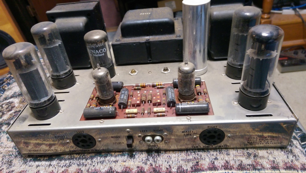
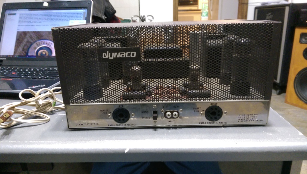
That looks like an unmolested example of an early (Powelton Avenue) 70. (19104 is West Philadelphia, University City). It could also be an early Jefferson Street model (Strawberry Mansion area) as it could be left-over sheet metal. Neatly assembled and very well kept.
I would, before passing go, and before collecting $200, clean the bias pots. Then, using a fine-pitch ammeter, bring it up on a variac and see what sort of current it is drawing. If reasonable, wait about 20 minutes, then set the bias. Ideally, you will short the input jacks when doing this to be sure the amp is stable. You want to be somewhere between 165 and 180 watts, max, at ramp-up, with no signs of heat or distress, and no red-plating on the output tubes or rectifier. If possible, observe the tubes in the dark. A blue glow is fine. But any hint of red-plating, shut-down instantly.
Various steps > I < would take before letting this amp loose on my speakers unsupervised (OK for testing, of course), in rank order:
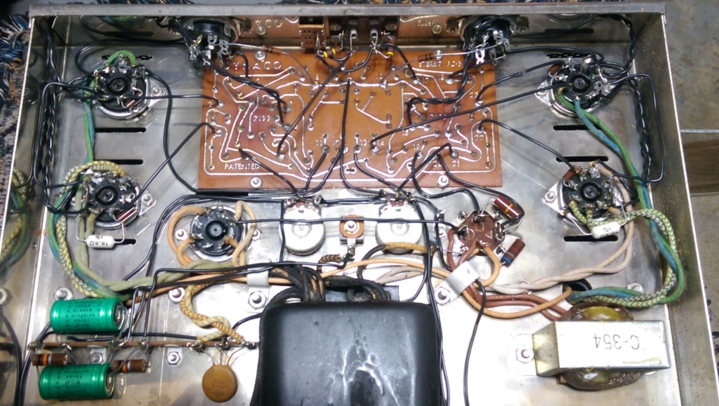
a) Mechanical check of all connections. I use a hooked dental pick to pull on each connection.
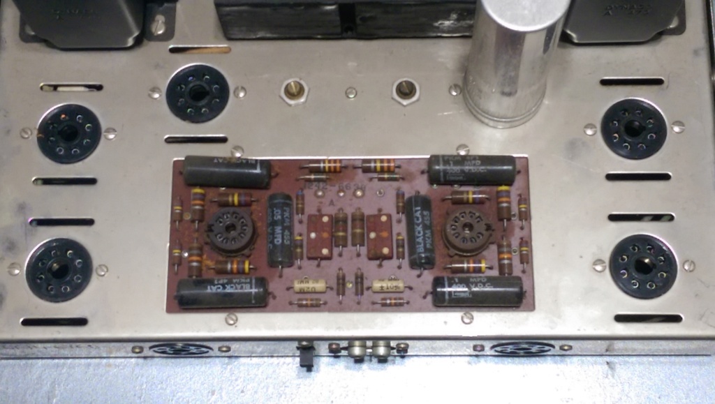
b) Careful inspection of the driver board for cracked or lifting traces, and tube socket damage.
c) Clean and tighten tube sockets with special reference to output and rectifier tubes. A dental pick, high-proof Isopropyl alcohol and miniature spiral brushes (Or fine pipe-cleaners) are your best friends.
d) Replacement of the selenium rectifier, bias-supply caps and bias resistor mod.
e) Total recap of the driver board using screened film resistors.
f) At least an ESR meter test of the filter caps (4-section cap). The caps used on these early units, in my experience, have been remarkably resilient, needing replacement far less often than later-run units.
g) If there are no grommets around the transformer lead penetrations, I would add them. You DO NOT have to disconnect anything, just purchase the correct grommets, slit them with an X-Acto knife and install them. A tiny drop of super-glue (grommet-to-chassis) to hold them in place is OK, but only if it makes you feel better.
NOTE:
NEVER, repeat NEVER use super-glue to secure a loose octal tube to its base. SG does not tolerate expansion well, and may actually crack the tube. Use a bit of silicon (heat resistant) instead.
A good find at a decent price!
Congrats!

Dale Stevens- Posts : 205
Join date : 2014-07-06
Age : 75
Location : Loris, SC
- Post n°4
 Re: just got this puppy :)
Peter, you are a jewel ! Dale

dmagazz- Posts : 147
Join date : 2018-06-20
Age : 56
Location : new fairf, ct
- Post n°5
 Re: just got this puppy :)
WOW!!! thanks so much peter.
incredible! input
i just copied and pasted that all into a text ive labeled My Dyna, and bordered it with asterisks.
i have a great checklist to go through.
ive ordered this kit
DYNACO-DYNAKIT-ST70-Tube-Amplifier-Diode-Kit- (D544042R) replaces-Selenium-Rectifier
i wonder, does that include the resistors for the mod you spoke of?
and im bound for a 525v 30/20/20/20 dynaco cap
i wasnt sure id have to mess with the driver board,
but ill be looking into a good bit of elna caps for it.
or is there a better option?

Peter W.- Posts : 1351
Join date : 2016-08-07
Location : Melrose Park, PA
- Post n°6
 Re: just got this puppy :)
or is there a better option?[/quote]
Well......
At the risk of many sore toes out there, after a certain basic level of quality is met, and the correct-for-the-purpose cap is chosen, a cap is pretty much a cap is pretty much a cap. I screen my caps so that they are within a percent or so channel-to-channel, something that is remarkably easy to do these days. That percent-or-so is, really, the limits of my meter, so I will not pretend to be able to do any better than that.
Above all else, enjoy!

dmagazz- Posts : 147
Join date : 2018-06-20
Age : 56
Location : new fairf, ct
- Post n°7
 Re: just got this puppy :)
after a certain basic level of quality is met, and the correct-for-the-purpose cap is chosen, a cap is pretty much a cap is pretty much a cap
see, now thats what ive always thought,
and i ran into a thread about capping a hk730 that a guy put up that as a scientist he soldered/unsoldered..over and over testing different caps in his unit to actually test the results.
i admit its a little subjective, as it is one persons ear of opinion,and 1 particular style circuit,
but it was an amazing thead i got hooked into
this is it, it starts with a user named patfont.
i still cant post links..so add the prefix to the string below
audiokarma.org/forums/index.php?threads/electrolytic-capacitor-shoot-out.381961
but that thread is referencing solid state,whole different animal right? a tube amp doesnt work tone in the same method as a SS amp does, does it.
i think im just gonna go for the dynaco branded stuff
Last edited by dmagazz on Sat Jun 23, 2018 9:32 am; edited 1 time in total

deepee99- Posts : 2244
Join date : 2012-05-23
Location : Wallace, Idaho
- Post n°8
 Re: just got this puppy :)
Peter W. wrote:That looks like an unmolested example of an early (Powelton Avenue) 70. (19104 is West Philadelphia, University City). It could also be an early Jefferson Street model (Strawberry Mansion area) as it could be left-over sheet metal. Neatly assembled and very well kept.
I would, before passing go, and before collecting $200, clean the bias pots. Then, using a fine-pitch ammeter, bring it up on a variac and see what sort of current it is drawing. If reasonable, wait about 20 minutes, then set the bias. Ideally, you will short the input jacks when doing this to be sure the amp is stable. You want to be somewhere between 165 and 180 watts, max, at ramp-up, with no signs of heat or distress, and no red-plating on the output tubes or rectifier. If possible, observe the tubes in the dark. A blue glow is fine. But any hint of red-plating, shut-down instantly.
Various steps > I < would take before letting this amp loose on my speakers unsupervised (OK for testing, of course), in rank order:
a) Mechanical check of all connections. I use a hooked dental pick to pull on each connection.
b) Careful inspection of the driver board for cracked or lifting traces, and tube socket damage.
c) Clean and tighten tube sockets with special reference to output and rectifier tubes. A dental pick, high-proof Isopropyl alcohol and miniature spiral brushes (Or fine pipe-cleaners) are your best friends.
d) Replacement of the selenium rectifier, bias-supply caps and bias resistor mod.
e) Total recap of the driver board using screened film resistors.
f) At least an ESR meter test of the filter caps (4-section cap). The caps used on these early units, in my experience, have been remarkably resilient, needing replacement far less often than later-run units.
g) If there are no grommets around the transformer lead penetrations, I would add them. You DO NOT have to disconnect anything, just purchase the correct grommets, slit them with an X-Acto knife and install them. A tiny drop of super-glue (grommet-to-chassis) to hold them in place is OK, but only if it makes you feel better.
NOTE:
NEVER, repeat NEVER use super-glue to secure a loose octal tube to its base. SG does not tolerate expansion well, and may actually crack the tube. Use a bit of silicon (heat resistant) instead.
A good find at a decent price!
Congrats!
Congrats indeed. Peter, one thing I would add to your list. In addition to shorting the inputs, ALWAYS have a ~ 8 ohm load on the outputs when the amp is on. This might be self-evident to most of us, but you'd be surprised. Just my tuppence worth.

deepee99- Posts : 2244
Join date : 2012-05-23
Location : Wallace, Idaho
- Post n°9
 Re: just got this puppy :)
Peter W. wrote:That looks like an unmolested example of an early (Powelton Avenue) 70. (19104 is West Philadelphia, University City). It could also be an early Jefferson Street model (Strawberry Mansion area) as it could be left-over sheet metal. Neatly assembled and very well kept.
I would, before passing go, and before collecting $200, clean the bias pots. Then, using a fine-pitch ammeter, bring it up on a variac and see what sort of current it is drawing. If reasonable, wait about 20 minutes, then set the bias. Ideally, you will short the input jacks when doing this to be sure the amp is stable. You want to be somewhere between 165 and 180 watts, max, at ramp-up, with no signs of heat or distress, and no red-plating on the output tubes or rectifier. If possible, observe the tubes in the dark. A blue glow is fine. But any hint of red-plating, shut-down instantly.
Various steps > I < would take before letting this amp loose on my speakers unsupervised (OK for testing, of course), in rank order:
a) Mechanical check of all connections. I use a hooked dental pick to pull on each connection.
b) Careful inspection of the driver board for cracked or lifting traces, and tube socket damage.
c) Clean and tighten tube sockets with special reference to output and rectifier tubes. A dental pick, high-proof Isopropyl alcohol and miniature spiral brushes (Or fine pipe-cleaners) are your best friends.
d) Replacement of the selenium rectifier, bias-supply caps and bias resistor mod.
e) Total recap of the driver board using screened film resistors.
f) At least an ESR meter test of the filter caps (4-section cap). The caps used on these early units, in my experience, have been remarkably resilient, needing replacement far less often than later-run units.
g) If there are no grommets around the transformer lead penetrations, I would add them. You DO NOT have to disconnect anything, just purchase the correct grommets, slit them with an X-Acto knife and install them. A tiny drop of super-glue (grommet-to-chassis) to hold them in place is OK, but only if it makes you feel better.
NOTE:
NEVER, repeat NEVER use super-glue to secure a loose octal tube to its base. SG does not tolerate expansion well, and may actually crack the tube. Use a bit of silicon (heat resistant) instead.
A good find at a decent price!
Congrats!
Congrats indeed. Peter, one thing I would add to your list. In addition to shorting the inputs, ALWAYS have a ~ 8 ohm load on the outputs when the amp is on. This might be self-evident to most of us, but you'd be surprised. Just my tuppence worth.

dmagazz- Posts : 147
Join date : 2018-06-20
Age : 56
Location : new fairf, ct
- Post n°10
 Re: just got this puppy :)
a) Mechanical check of all connections. I use a hooked dental pick to pull on each connection.
b) Careful inspection of the driver board for cracked or lifting traces, and tube socket damage.
c) Clean and tighten tube sockets with special reference to output and rectifier tubes. A dental pick, high-proof Isopropyl alcohol and miniature spiral brushes (Or fine pipe-cleaners) are your best friends.
d) Replacement of the selenium rectifier, bias-supply caps and bias resistor mod.
e) Total recap of the driver board using screened film resistors.
f) At least an ESR meter test of the filter caps (4-section cap). The caps used on these early units, in my experience, have been remarkably resilient, needing replacement far less often than later-run units.
g) If there are no grommets around the transformer lead penetrations, I would add them. You DO NOT have to disconnect anything, just purchase the correct grommets, slit them with an X-Acto knife and install them. A tiny drop of super-glue (grommet-to-chassis) to hold them in place is OK, but only if it makes you feel better.
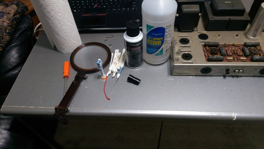
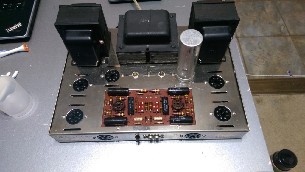
just got through with the cleaning and inspections.
almost wiped away the print on the tubes, the tranny too.
everything was actually ok!
i did snug up some tube connectors that looked a little large to me.
also took some tuner cleaner to the switches and pots.
hooked up the speakers,
and reset the bios after spinning the pots back and forth a bit(while it was off of corse)
then hooked up some pigtail rca plugs that i had laying around and shorted the leads for the preamp hum test.. and yyyea.... very nice
the force is with this one
now its on to D,E,F, and G
here are before,before and after


dmagazz- Posts : 147
Join date : 2018-06-20
Age : 56
Location : new fairf, ct
- Post n°11
 Re: just got this puppy :)
just ordered a 80,40,20,20 525v cap
and the caps for the driver board from dynakitparts.com
should have them just after i get the bios diode kit.
then i can continue my venture given me by peter.
CANT WAIT.....
d) Replacement of the selenium rectifier, bias-supply caps and bias resistor mod.
e) Total recap of the driver board using screened film resistors.
f) At least an ESR meter test of the filter caps (4-section cap). The caps used on these early units, in my experience, have been remarkably resilient, needing replacement far less often than later-run units.
g) If there are no grommets around the transformer lead penetrations, I would add them. You DO NOT have to disconnect anything, just purchase the correct grommets, slit them with an X-Acto knife and install them. A tiny drop of super-glue (grommet-to-chassis) to hold them in place is OK, but only if it makes you feel better.

audiobill- Posts : 425
Join date : 2014-03-13
Location : Albany, NY
- Post n°12
 Re: just got this puppy :)
You may wish to also replace the input jacks with gold plated.

dmagazz- Posts : 147
Join date : 2018-06-20
Age : 56
Location : new fairf, ct
- Post n°13
 Re: just got this puppy :)
they seem ok, pretty darn clean.
i had considered changing alot of things at first, i was ready to go gung ho!.lol
but i think ill keep it as close as true to original for now.
by the way did you see the wacky Zenith selenium rectifier i posted in the basket?
i had considered changing alot of things at first, i was ready to go gung ho!.lol
but i think ill keep it as close as true to original for now.
by the way did you see the wacky Zenith selenium rectifier i posted in the basket?

deepee99- Posts : 2244
Join date : 2012-05-23
Location : Wallace, Idaho
- Post n°14
 Re: just got this puppy :)
Isn't there a substrate holding the gold onto its Zn that ceases to conduct?audiobill wrote:You may wish to also replace the input jacks with gold plated.

Peter W.- Posts : 1351
Join date : 2016-08-07
Location : Melrose Park, PA
- Post n°15
 Re: just got this puppy :)
deepee99 wrote:Isn't there a substrate holding the gold onto its Zn that ceases to conduct?audiobill wrote:You may wish to also replace the input jacks with gold plated.
"Proper" plating protocol is base-metal + copper + gold. This reduces the incidence of "gold whiskers" amongst other problems. If zinc is involved, or aluminum, many problems can take place if the plating is not perfect, or any of the baths were contaminated. c.f. Purple Plague as one example. But, most connectors in the Audio business, such as tube socket connectors and such-like are tin-plated bronze, made without zinc - at least the good ones.
For the record - and wearing my NASA-approved Rocket-blast flame-suit:
GOLD PLATING for audio products as a BAD IDEA.
a) Gold is a poor conductor, as compared to copper or silver, even cadmium-plated tin.
b) If the substrate is not perfect, the plating will fail. The causes for failure are multiple.
c) It is pretty however.
Decent-quality bright-plated patch-cords and decent-quality bright-plated sockets/connectors are as good as it gets, unless one is NASA, and needs the gold-plating against extremely harsh conditions. And, even NASA has 'lost' devices to both tin whiskers and gold whiskers when the plating failed. Good connections are key, of course.

dmagazz- Posts : 147
Join date : 2018-06-20
Age : 56
Location : new fairf, ct
- Post n°16
 Re: just got this puppy :)
yep, my thought was usually there is a etching process for plating, i am going to use old true to date type "solder on" steel connectors, my thought is 2 like metals will be less likely to cause corrosion,and will connect to each other better than 2 dissimilar ones, also the solder,and the wire its connected to isn't gold, so whats the actual use. but that is just my opinion. i would doubt there was any substantial audible difference at all. does anyone have evidence otherwise?
on another note, getting back to the diode kit for the bios(removing the selenium rectifier) if the voltage increases a bit making it too sketchy to adjust the bios with the pot's, is it possible that a pair of voltage parasitic voltmeters may decrease it to a adjustable level? so as not having to change the resistors at the tube sockets?
on another note, getting back to the diode kit for the bios(removing the selenium rectifier) if the voltage increases a bit making it too sketchy to adjust the bios with the pot's, is it possible that a pair of voltage parasitic voltmeters may decrease it to a adjustable level? so as not having to change the resistors at the tube sockets?

dmagazz- Posts : 147
Join date : 2018-06-20
Age : 56
Location : new fairf, ct
- Post n°17
 Re: just got this puppy :)
peter, good call.. gold whiskers!
found this
nepp.nasa.gov/whisker/other_whisker/gold/2003-teverovsky-gold-whiskers.pdf
found this
nepp.nasa.gov/whisker/other_whisker/gold/2003-teverovsky-gold-whiskers.pdf

deepee99- Posts : 2244
Join date : 2012-05-23
Location : Wallace, Idaho
- Post n°18
 Re: just got this puppy :)
Having had a slight blush with metallurgy over the years, I've found that most folks don't realise that silver is a better conductor than Au. And also, though it tarnishes (unlike gold, which doesn't) will retain its conductivity far better than Cu or Zn. Copper and zinc tend to oxidize, whereas most silver tarnish is in the sulfide form and remains conductive. If somebody made solid silver-pinned tubes I would buy them, provided they went in to silver sockets.Peter W. wrote:deepee99 wrote:Isn't there a substrate holding the gold onto its Zn that ceases to conduct?audiobill wrote:You may wish to also replace the input jacks with gold plated.
"Proper" plating protocol is base-metal + copper + gold. This reduces the incidence of "gold whiskers" amongst other problems. If zinc is involved, or aluminum, many problems can take place if the plating is not perfect, or any of the baths were contaminated. c.f. Purple Plague as one example. But, most connectors in the Audio business, such as tube socket connectors and such-like are tin-plated bronze, made without zinc - at least the good ones.
For the record - and wearing my NASA-approved Rocket-blast flame-suit:
GOLD PLATING for audio products as a BAD IDEA.
a) Gold is a poor conductor, as compared to copper or silver, even cadmium-plated tin.
b) If the substrate is not perfect, the plating will fail. The causes for failure are multiple.
c) It is pretty however.
Decent-quality bright-plated patch-cords and decent-quality bright-plated sockets/connectors are as good as it gets, unless one is NASA, and needs the gold-plating against extremely harsh conditions. And, even NASA has 'lost' devices to both tin whiskers and gold whiskers when the plating failed. Good connections are key, of course.

audiobill- Posts : 425
Join date : 2014-03-13
Location : Albany, NY
- Post n°19
 Re: just got this puppy :)
dmagazz, just a friendly pointer that the word is bias, not bios........

dmagazz- Posts : 147
Join date : 2018-06-20
Age : 56
Location : new fairf, ct
- Post n°20
 Re: just got this puppy :)
lol, actually. i caught on to that earlier today. thanks autobill.im more familiar with its use in computer language. didn't give it a second thought.

