The Dynaco Tube Audio Forum

Would you like to react to this message? Create an account in a few clicks or log in to continue.
The Dynaco Tube Audio Forum

Dedicated to the restoration and preservation of all original Dynaco tube audio equipment - Customer support for Tubes4hifi VTA tube amp and preamp kits and all Dynakitparts.com products


4 posters

    Please help me finish my PAS-2 upgrade

    avatar
    Guest
    Guest


    Please help me finish my PAS-2 upgrade - Page 4 Empty Re: Please help me finish my PAS-2 upgrade

    Post by Guest Wed Dec 05, 2018 11:31 pm

    Bill,

    I just sent you a new 'pm'
    billinrio
    billinrio


    Posts : 107
    Join date : 2018-01-03

    Please help me finish my PAS-2 upgrade - Page 4 Empty Re: Please help me finish my PAS-2 upgrade

    Post by billinrio Thu Dec 06, 2018 10:21 am

    DynakitParts wrote:Bill,
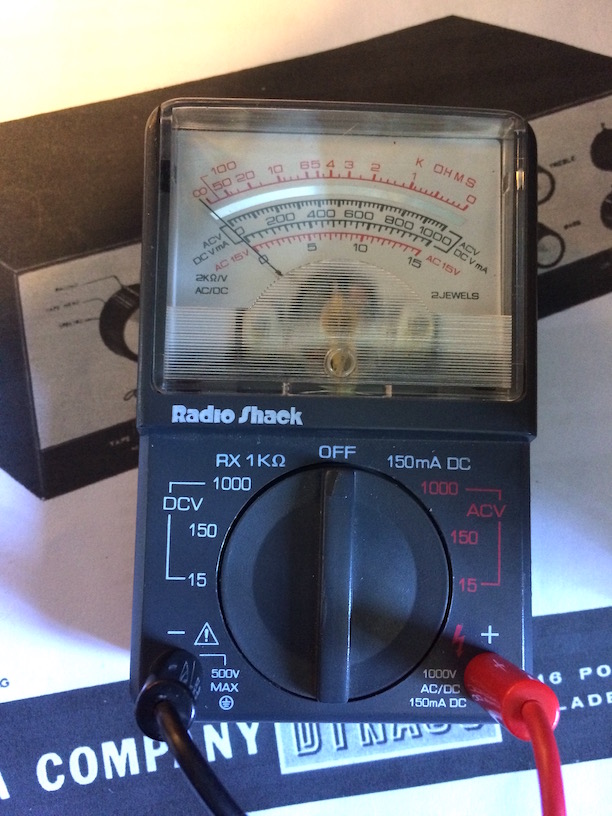
         The 330-0-330 secondary voltage spec is based on full load. You measured 324-0-324 vac under no load. Figure about a 20 to 25 volt drop under full load.

    So...the high voltage secondary under no load should have been roughly 350-0-350 vac to 355-0-355 vac.

    The transformer appears to be defective. Why did they send you a dual voltage unit to begin with...did you request this?

    Kevin


    No, I didn't request a dual voltage transformer, but that's what they sent me.
    Peter W.
    Peter W.


    Posts : 1351
    Join date : 2016-08-07
    Location : Melrose Park, PA

    Please help me finish my PAS-2 upgrade - Page 4 Empty Re: Please help me finish my PAS-2 upgrade

    Post by Peter W. Thu Dec 06, 2018 2:53 pm

    Finally, I have to get off my fingers. I have resisted joining this thread until now as I observed much confusion and, together with much good advice, also advice that added (in my opinion) to the confusion.

    Starting out, I use a mid-end Fluke "True RMS" DVM with an 'analog' bar-graph to mimic a needle. Quite useful for showing 'dither'.

    There are a total of four (4) critical voltage points on the PAS. _all_ the others are quite flexible.  
    Voltages, generally, do not want to be more than 5% over.
    Voltages, generally, do not want to be more than 10% under.
    Take measurements at 120 VAC at the wallplate, as measured independently, with the unit ON. If necessary, use at least two (2) meters to verify the voltage.
    At 120 VAC, *both* primary windings should be in parallel. Otherwise, down-line voltages will be low. However, running them in parallel DOES NOT double the voltage, it does (very nearly) double the current produced. My preference is pretty much always leaning to dual-voltage transformers operating at the lower-of-two voltages for this reason.

    All voltages below with all tubes in place (loaded).

    The 12X4 is a 7-pin miniature. Clockwise, from the bottom 1 - 7.

    Pin 1 & Pin 6 to chassis:  335 VAC. Meaning that the actual as-measured may be:
    From: 351.75 to 301V.
    Pin 7 to chassis: 405 VDC. Meaning that the actual as-measured may be:
    From 425.25 to 364.5 VDC.

    DC Filament voltage wants to be from 11 V to 13.6 V. WARNING: Operating 9-pin miniature 12**7 tubes at/above 13.0 V WILL shorten their lives, considerably. Below 10.8 V may lead to lazy cathode syndrome, but that is MAY, not WILL. But, that range is still within parameters.
    AC filament voltage (pins 3&4 on the 12X4 may be from 10 V to a full 12 V.

    All the other voltage processing is done on the boards or by the Quad-Cap RC array. What is key are the input voltages.

    What is coming from the transformer secondaries is within parameters - albeit at the margins.
    Voltages after that are not. Full stop.

    One of the reasons I stayed away is that diagnosis (and suggestions) at-a-distance is fraught with difficulties, and a simple turn-of-phrase may lead to a poor or damaging result. Things I take for granted, and directions given based on such my become misdirected. But despite all that, here goes:

    Bill:

    Put everything aside and out of sight-and-mind for 48 hours.
    I will assume you are retaining the 12X4
    On the new cap-board, REMOVE ALL WIRES. Reconnect in this order:
    Indicator lamp wires (black-black) to CN2A #1 and CN2 #2
    Blue-Blue filament winding wires from transformer to CN2A #2 and CN2 #1
    Red-Red B+ Winding wires to CN1 #2 & CN1 #3.
    Connect the wire at Pin 7 of the 12X4 to CN1 #1

    Install a ground-lug under the chassis with either a KEP-nut or lock-washer on the front-most transformer bolt. THAT will be your common ground from the transformer, and from the PCBs, and from the new cap board (AKA "Star" ground).

    Take a twisted-pair from the ground points on the cap-board to the new lug.

    Now test for voltages (to the chassis) at CN 3 & 4. And report back. No load on the board.

    We will go on from there.
    billinrio
    billinrio


    Posts : 107
    Join date : 2018-01-03

    Please help me finish my PAS-2 upgrade - Page 4 Empty Re: Please help me finish my PAS-2 upgrade

    Post by billinrio Fri Dec 07, 2018 6:45 am

    Hi Peter.  I'm glad that you have been following this. I fully understand what you say about the perils of misunderstanding at a distance and the possibility of resulting damage to equipment or to health.  High voltages can be nasty when not respected.

    I am retaining the 12X4.

    In a reply (when the cap board seller was still responding to my mails, which is no longer the case), he wrote:

    "1. Better use a DMM to check the transformer output voltage of the RED pair and the BLUE pair of wires first" (by 'first' he means "before connecting the transformer leads to the board and to the 12X4")

    "2. If the BLUE pair output voltage is 10.5V AC, then correct them to CN2 & CN2A at the cap board."

    "3. IF the RED pair output voltage is 335V AC , then one RED wire should connect to 12X4 pin 1 and the other RED wire should connect to 12X4 pin 6. The DC output of 12X4 pin 7 should be connected to CN1 -12x4 on the cap board."

    "4. Don't connect the RED wires to CN1 - RED RED on the cap board.  CN1 RED RED is for testing only."
    billinrio
    billinrio


    Posts : 107
    Join date : 2018-01-03

    Please help me finish my PAS-2 upgrade - Page 4 Empty Re: Please help me finish my PAS-2 upgrade

    Post by billinrio Sat Dec 08, 2018 3:35 pm

    It's only #4 above that concerns me.  I don't understand why "Red" is even written on the cap board at CN1, given that "Blue" is written at CN2 and at CN2A, and that is indeed where the blue transformer wires are to be connected.
    avatar
    Guest
    Guest


    Please help me finish my PAS-2 upgrade - Page 4 Empty Re: Please help me finish my PAS-2 upgrade

    Post by Guest Sat Dec 08, 2018 5:47 pm

    .


    Last edited by PeterCapo on Mon Nov 30, 2020 8:53 pm; edited 1 time in total
    billinrio
    billinrio


    Posts : 107
    Join date : 2018-01-03

    Please help me finish my PAS-2 upgrade - Page 4 Empty Re: Please help me finish my PAS-2 upgrade

    Post by billinrio Sun Dec 09, 2018 8:04 am

    Thanks for your explanation.  
    My quoting of point No.4 of the cap board seller's instructions: "Don't connect the RED wires to CN1 - RED RED on the cap board.  CN1 RED RED is for testing only" was really due to the fact that in Post #78 that's precisely what I am instructed to do.
    avatar
    Guest
    Guest


    Please help me finish my PAS-2 upgrade - Page 4 Empty Re: Please help me finish my PAS-2 upgrade

    Post by Guest Sun Dec 09, 2018 2:54 pm

    .


    Last edited by PeterCapo on Fri Dec 04, 2020 12:22 pm; edited 4 times in total
    billinrio
    billinrio


    Posts : 107
    Join date : 2018-01-03

    Please help me finish my PAS-2 upgrade - Page 4 Empty Re: Please help me finish my PAS-2 upgrade

    Post by billinrio Sun Dec 09, 2018 3:15 pm

    PeterCapo wrote:It's a long thread, and it would be easy to miss details ...

    But, if anyone can get your voltages to line up closely with the chart without a new power transformer, and without using nonstandard component values or making other changes to the circuit, I’m all ears.

    I am all ears as well.

    I'm wary about accepting wide deviations of voltage and  just hooking the preamp as it is into my system and seeing what happens.  I wouldn't be satisfied  merely by the fact of not having a complete lack of sound. My goal, of course, if for the preamp to perform optimally.

    I contacted Triode and they replied three days ago, "I will pass this on to your tech and of course, we will back up the transformer if it is defective.
    Thank you,
    Jan"

    I'm not sure what "back up" means, especially because they delivered the transformer to me when I was at a U.S. address, and now we have to deal
    with expensive international mail rates for (if they so require) my returning the transformer to them, and then (if they agree that it is indeed defective) shipping me another one.  The cost of shipping the transformer to them and then for me to receive one back from them would be at least, and probably more than the original cost of the transformer itself.


    Last edited by billinrio on Sun Dec 09, 2018 7:10 pm; edited 1 time in total
    avatar
    Guest
    Guest


    Please help me finish my PAS-2 upgrade - Page 4 Empty Re: Please help me finish my PAS-2 upgrade

    Post by Guest Sun Dec 09, 2018 4:34 pm

    .


    Last edited by PeterCapo on Mon Nov 30, 2020 8:53 pm; edited 1 time in total
    avatar
    Guest
    Guest


    Please help me finish my PAS-2 upgrade - Page 4 Empty Re: Please help me finish my PAS-2 upgrade

    Post by Guest Sun Dec 09, 2018 9:07 pm

    .


    Last edited by PeterCapo on Mon Nov 30, 2020 8:52 pm; edited 1 time in total
    billinrio
    billinrio


    Posts : 107
    Join date : 2018-01-03

    Please help me finish my PAS-2 upgrade - Page 4 Empty Re: Please help me finish my PAS-2 upgrade

    Post by billinrio Mon Dec 10, 2018 6:26 am

    PeterCapo wrote:I'd be concerned that another transformer from Triode might have a similar problem.  I know dynakitparts.com makes quality stuff.  Especially after all this, I'd personally want to go with the dynakitparts transformer, but, of course, it's your call.

    While you are waiting on resolving the power transformer, you could still check out some other things.  While I think it would be preferable to have a power transformer that is performing really well, you could still have other issues even with a perfect transformer (if there were such a thing).  A new transformer cannot do anything to help miswiring, incorrect component values, defective parts, etc.  In particular, your last voltage readings at PC5 tube socket pins 1 were about 35% low.  Not sure the transformer can explain a discrepancy as large as this.

    Here are a few things to check:

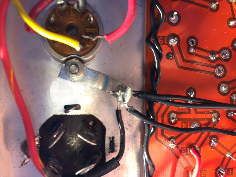
    1. Please correct me if I have it wrong, but I believe Peter W. was suggesting removing the wires from CN4-1 and CN4-2 and then taking the unloaded voltage readings at each one (and the same for the filaments at the CN3 outputs).  In taking the unloaded readings, it would be prudent to monitor the voltage across the capacitors on the cap board while slowly increasing the variac.  Two hurdles.  First, you'd need to know the voltage ratings of all six capacitors, and hopefully they are marked in a readable format and not in some kind of cryptic part# coding.  You'd also need to know where to measure the voltages across them, which could get confusing.

    2. Peter W. also suggested rechecking the wiring to the cap board, which is always a good idea.

    3. You could also have a look back at Post n°54, which is what I had in mind before the transformer took center stage.  

    3.5 As we have suggested, verifying readings with a second meter would be a really good idea.

    4. One other thought for now...  When you took the unloaded readings of the two red wires of the power transformer, you said that you left the red-yellow center tap wire connected to your chassis ground point, is that correct?  You'd just want to make sure that while one lead of the meter was on each red wire in turn that the other meter lead would directly contact the red-yellow wire.  To eliminate any doubt, you could try removing the red-yellow wire from the ground point and make the measurement directly between each red wire in turn and the disconnected red-yellow center tap wire.  Hope that makes sense.

    5. I believe Peter W. was also suggesting revisiting/shoring up your ground point.  If you don't have a proper ground, it could cause problems.

    Hope we will get some more input from others.

    Here are some photos of the caps on the board:
    Please help me finish my PAS-2 upgrade - Page 4 Caps%20on%20board_zpsu7q099fq
    Please help me finish my PAS-2 upgrade - Page 4 More%20caps%20on%20board_zpshvmytvqm

    And this is my "second meter" (no joke). So, I really can't rely on it.  I would love to have a Fluke, but ....

    Please help me finish my PAS-2 upgrade - Page 4 RS%20meter_zpsiqwajhlh

    I've created a single chassis ground connection:
    Please help me finish my PAS-2 upgrade - Page 4 Ground_zpsmey1g8s2
    billinrio
    billinrio


    Posts : 107
    Join date : 2018-01-03

    Please help me finish my PAS-2 upgrade - Page 4 Empty Re: Please help me finish my PAS-2 upgrade

    Post by billinrio Mon Dec 10, 2018 10:41 am

    Here are the capacitor measurements, all at 120VAC.
    Voltage across C1: one meter lead on CN1-1 and the other to ground: 442V
    Voltage across C2: one meter lead on the junction of the 47K resistor and the two 10K resistors and the other lead to ground: 434V
    Voltage across C3 and C5:one meter lead on CN4-1 and the other to ground:412V
    Voltage across C4 and C6:one meter lead on CN4-2 and the other lead to ground:425V
    Voltage across C7: one meter lead on CN3-1 and the other lead on CN2A-1: 16.3V
    Voltage across C8: one meter lead on CN2A-1 and the other lead on CN3A-1: 16.3V[/b]


    When you day, "please report the readings at CN4-1, CN4-2, CN3-1, CN3-2, CN3A-1, and CN3A-2".
    Are the readings with the wires still removed from these points, or with the wires reconnected?


    Last edited by billinrio on Mon Dec 10, 2018 11:15 am; edited 1 time in total
    avatar
    Guest
    Guest


    Please help me finish my PAS-2 upgrade - Page 4 Empty Re: Please help me finish my PAS-2 upgrade

    Post by Guest Mon Dec 10, 2018 11:14 am

    .


    Last edited by PeterCapo on Mon Nov 30, 2020 8:52 pm; edited 1 time in total
    Peter W.
    Peter W.


    Posts : 1351
    Join date : 2016-08-07
    Location : Melrose Park, PA

    Please help me finish my PAS-2 upgrade - Page 4 Empty Re: Please help me finish my PAS-2 upgrade

    Post by Peter W. Mon Dec 10, 2018 11:31 am

    PeterCapo wrote:I'd like to know what Peter W. thinks about those readings...

    They are all massively too high. From which I may draw only three (3) conclusions - and these I will list in rank order of likelihood in my mind:

    a) The measuring meter(s) is(are) defective.
    b) The cap board is defective.
    c) The new transformer is defective.

    The first set of readings was (apparently) too low.
    The next set of readings is too high. Wish I was there.

    At 120 VAC at the wallplate, the reading on the filament winding should be somewhere around 11 VAC under load!

    Bill:

    Please adjust your Variac until the reading on the filament wires (blue/blue) when connected to the 12X4 reads 11 VAC. Then recheck the other readings. Please let us know.

    Thanks!
    avatar
    Guest
    Guest


    Please help me finish my PAS-2 upgrade - Page 4 Empty Re: Please help me finish my PAS-2 upgrade

    Post by Guest Mon Dec 10, 2018 11:36 am

    .


    Last edited by PeterCapo on Mon Nov 30, 2020 8:51 pm; edited 1 time in total
    Peter W.
    Peter W.


    Posts : 1351
    Join date : 2016-08-07
    Location : Melrose Park, PA

    Please help me finish my PAS-2 upgrade - Page 4 Empty Re: Please help me finish my PAS-2 upgrade

    Post by Peter W. Mon Dec 10, 2018 11:45 am

    PeterCapo wrote:But they are unloaded.  Shouldn't they be higher than when loaded?

    If they are way too high, how do we account for one of the nodes on PC5 being 35% low? And te unloaded output from the transformer being low?  This whole thing has been a portrait in contradictions.

    Exactly that. And the common denominator to a large series of conflicting readings is the meters being used to do them.

    Once upon a time, I had a Hickok tube tester with a failing 83 in it. Plenty of current for a low-signal tube, not enough for a power pentode, or even a 2A3. That is how I learned a  hard lesson on calibrating and testing test-equipment prior to any sort of potentially serious (costly) diagnosis.

    I am guessing that ten minutes on either of our benches would get to the bottom of this. But diagnosis-at-a-distance is difficult, even with experts on either end.

    But-for the filament winding, I would like readings to the chassis, (ground), not to another point on the cab board.
    avatar
    Guest
    Guest


    Please help me finish my PAS-2 upgrade - Page 4 Empty Re: Please help me finish my PAS-2 upgrade

    Post by Guest Mon Dec 10, 2018 12:01 pm

    .


    Last edited by PeterCapo on Mon Nov 30, 2020 8:51 pm; edited 1 time in total
    avatar
    Guest
    Guest


    Please help me finish my PAS-2 upgrade - Page 4 Empty Re: Please help me finish my PAS-2 upgrade

    Post by Guest Mon Dec 10, 2018 12:03 pm

    .


    Last edited by PeterCapo on Mon Nov 30, 2020 8:51 pm; edited 1 time in total
    billinrio
    billinrio


    Posts : 107
    Join date : 2018-01-03

    Please help me finish my PAS-2 upgrade - Page 4 Empty Re: Please help me finish my PAS-2 upgrade

    Post by billinrio Mon Dec 10, 2018 12:37 pm

    The meter (a Wavetek DM5XL) has a fresh 9v battery. I've looked through the manual. It doesn't have a calibration feature.
    avatar
    Guest
    Guest


    Please help me finish my PAS-2 upgrade - Page 4 Empty Re: Please help me finish my PAS-2 upgrade

    Post by Guest Mon Dec 10, 2018 12:49 pm

    .


    Last edited by PeterCapo on Mon Nov 30, 2020 8:50 pm; edited 2 times in total
    avatar
    Guest
    Guest


    Please help me finish my PAS-2 upgrade - Page 4 Empty Re: Please help me finish my PAS-2 upgrade

    Post by Guest Mon Dec 10, 2018 12:58 pm

    .


    Last edited by PeterCapo on Mon Nov 30, 2020 8:50 pm; edited 1 time in total
    billinrio
    billinrio


    Posts : 107
    Join date : 2018-01-03

    Please help me finish my PAS-2 upgrade - Page 4 Empty Re: Please help me finish my PAS-2 upgrade

    Post by billinrio Mon Dec 10, 2018 1:25 pm

    Peter W. wrote:
    PeterCapo wrote:I'd like to know what Peter W. thinks about those readings...

    Bill:

    Please adjust your Variac until the reading on the filament wires (blue/blue) when connected to the 12X4 reads 11 VAC. Then recheck the other readings. Please let us know.

    Thanks!

    Umm.... there are no blue/blue wires connected to the 12X4. Do you mean the heater supply wires that go to CN2A-2 and CN2-1?
    avatar
    Guest
    Guest


    Please help me finish my PAS-2 upgrade - Page 4 Empty Re: Please help me finish my PAS-2 upgrade

    Post by Guest Mon Dec 10, 2018 1:37 pm

    .


    Last edited by PeterCapo on Mon Nov 30, 2020 8:50 pm; edited 1 time in total
    Peter W.
    Peter W.


    Posts : 1351
    Join date : 2016-08-07
    Location : Melrose Park, PA

    Please help me finish my PAS-2 upgrade - Page 4 Empty Re: Please help me finish my PAS-2 upgrade

    Post by Peter W. Mon Dec 10, 2018 2:22 pm

    PeterCapo wrote:I think he meant for you to measure the filament supply output with the cap board loaded again.  The Triode PT specs at 12 volts for the filaments with 120 VAC mains.  Your readings unloaded were much higher.

    Look, I think we have to distinguish between loaded and unloaded figures.  The unloaded figures will be higher than loaded figures, but we don't have specs for what unloaded B+ and filaments should actually measure.

    At this point, I am in favor of:
    1) going to whatever lengths necessary to verify the values and proper locations of the three resistors on the cap board and also the resistors on PC5 that I asked about in Post n°96
    2) review the ground connections
    3) if 1 & 2 above seem okay, then I vote for a new dynakitparts power transformer

    That's it.  If anyone else has any other ideas, please speak up.

    WARNING: I am casting back to my dim-and-distant memory of Ohm's Law and the nature of rectifiers on this one. And, deriving from the OEM design. So I may be WAY off, but it does pencil.

    a) OEM uses a Full-Wave rectifier (NOT a bridge) across two selenium diodes, each one dropping about 1 volt in that configuration.
    b) The DC load on the filament supply is 1.2 A (150 ma x 8 )
    c) The AC load on the filament Winding is 300 ma.
    d) The theoretical voltage output from the transformer should be, unloaded, theoretically, again, about 12 AC volts. Theoretically, rectification (full wave) takes that to about 14.8 volts. The selenium diodes drop that back to about 12.8 VDC.
    e) Assign a resistance of 200 ohms (in series/parallel) net to the four tubes.
    f) Assign a 1-ohm forward-resistance to a silicon diode. It will be a little less.


    This calculates to 11.47 VDC, loaded.

    So, from this very rough calculation  - the voltage on the filament supply winding (unloaded) should be about 12 VAC. Or slightly higher as we have not factored the 12X4 300 MA current draw as a separate number.

    Loaded, the output from the filament supply should be ~11.5 VDC To the chassis. Unloaded (no tubes but the 12X4), it should be around 12.8 VDC to the chassis.

    I am functioning on the assumption that the Cap Board is meant to duplicate the voltages of the OEM supply, both filament and B+.
    I am functioning on the assumption that the new transformer has two (2) primary windings, and that they are connected in parallel.

    I want to get past the filament voltages before delving into the B+. If we do, we have at least one successful diagnosis.

    NOTE and FOR THE RECORD: I was a Fine Arts/Architecture undergraduate major. And although I took multiple engineering courses towards an MS, nothing in EE. My electrical knowledge is based on working my way through schools with the tools - not from a classroom.

    Sponsored content


    Please help me finish my PAS-2 upgrade - Page 4 Empty Re: Please help me finish my PAS-2 upgrade

    Post by Sponsored content


      Current date/time is Fri May 17, 2024 7:46 am