The Dynaco Tube Audio Forum

Would you like to react to this message? Create an account in a few clicks or log in to continue.
The Dynaco Tube Audio Forum

Dedicated to the restoration and preservation of all original Dynaco tube audio equipment - Customer support for Tubes4hifi VTA tube amp and preamp kits and all Dynakitparts.com products


4 posters

    Dynaco MKII Troubleshooting

    avatar
    drafalske


    Posts : 15
    Join date : 2015-10-11

    Dynaco MKII Troubleshooting Empty Dynaco MKII Troubleshooting

    Post by drafalske Thu Dec 13, 2018 6:07 pm

    Hi all. I'm working on an early Mark II that keeps blowing filter caps. I've traced the issue to high AC voltage on pins 2&8 of the rectifier.
    DMM leads attached to both pins shows normal 5.3vac.
    One lead to chassis ground and the other to either pin will show 137.6vac. This is with or without anything else attached to tube socket (rectifier inserted or not).
    Any ideas what's going on?
    WLT
    WLT


    Posts : 186
    Join date : 2013-07-13
    Location : Rochester NY

    Dynaco MKII Troubleshooting Empty Re: Dynaco MKII Troubleshooting

    Post by WLT Thu Dec 13, 2018 8:17 pm

    I am assuming you have the original manual or a copy. On the second to last page is a chart with voltage check points. 430 VAC to ground on pins 4 and 6. There should not be any AC voltage on pins 2 and 8. Only the 470 VDC once the rectifier is in and the amp is warmed up. There are very few ways that 137 VAC could get onto both pin 8 and pin 2. One option is a transformer short from a portion of the high voltage winding connecting to the 5 volt winding.

    Check the schematic to see why this should work. Pull the rectifier and measure resistance between pin (8 or 2) to pin (6 or 4). Try 8 to 6. If there is no short the meter should read a very high or infinite number. If it reads anything measurable then try 8 to 4. If it gives a measurable number but is not the same reading as the first one then I think the power transformer is shorted. Measure all four ways.

    Another option. Look carefully at the rectifier tube socket. Could it have some tracking marks that might provide some resistance but not a full short between pins 8/2 and pins 6/4? Just enough to put some AC where it is not needed.

    If the 117 VAC side of the transformer shorted to the 5 volt winding it would additive and only read 122VAC (or so). Check your house voltage and add the 5 volts to it. Still not enough to add up to 137 VAC. Check the 117 volt winding for resistance to the 5 volt winding. It should also be infinite.

    The other winding is 6.3 volts so it is doubtful that it is involved.

    Interesting problem. If the transformer is shorted one solution would be to install a separate 5 volt tranny and wire the two yellow leads to a terminal so they are not in the scheme.

    Good luck and let us know what you find.
    pichacker
    pichacker


    Posts : 103
    Join date : 2016-08-01
    Age : 59
    Location : Near to London - UK

    Dynaco MKII Troubleshooting Empty Re: Dynaco MKII Troubleshooting

    Post by pichacker Fri Dec 14, 2018 5:28 am

    If the OP is using a DMM to measure the voltage then of course it's input will be very high impedance so even a minute amount of leakage will show a reading. Given the tightness of the windings then capacitive coupling could in thoery create a stray reading. But i'd expect to read nothing if the pins are still connected to the rest of the circuit as this would provide some loading. If AC is still present in this case  (which the smoothing caps would not like) then "WLT" has good suggestions.

    If the worst has happened and the transformer has developed an internal short circuit then, providing no other windings are suspect, the rectifier could be replaced by an SS equivalent and the heater windings left disconnected.

    Once the OP has made a few more posts then a photograph could be posted for all to see. A Picture paints a thousand words.
    avatar
    drafalske


    Posts : 15
    Join date : 2015-10-11

    Dynaco MKII Troubleshooting Empty Re: Dynaco MKII Troubleshooting

    Post by drafalske Fri Dec 14, 2018 11:15 am

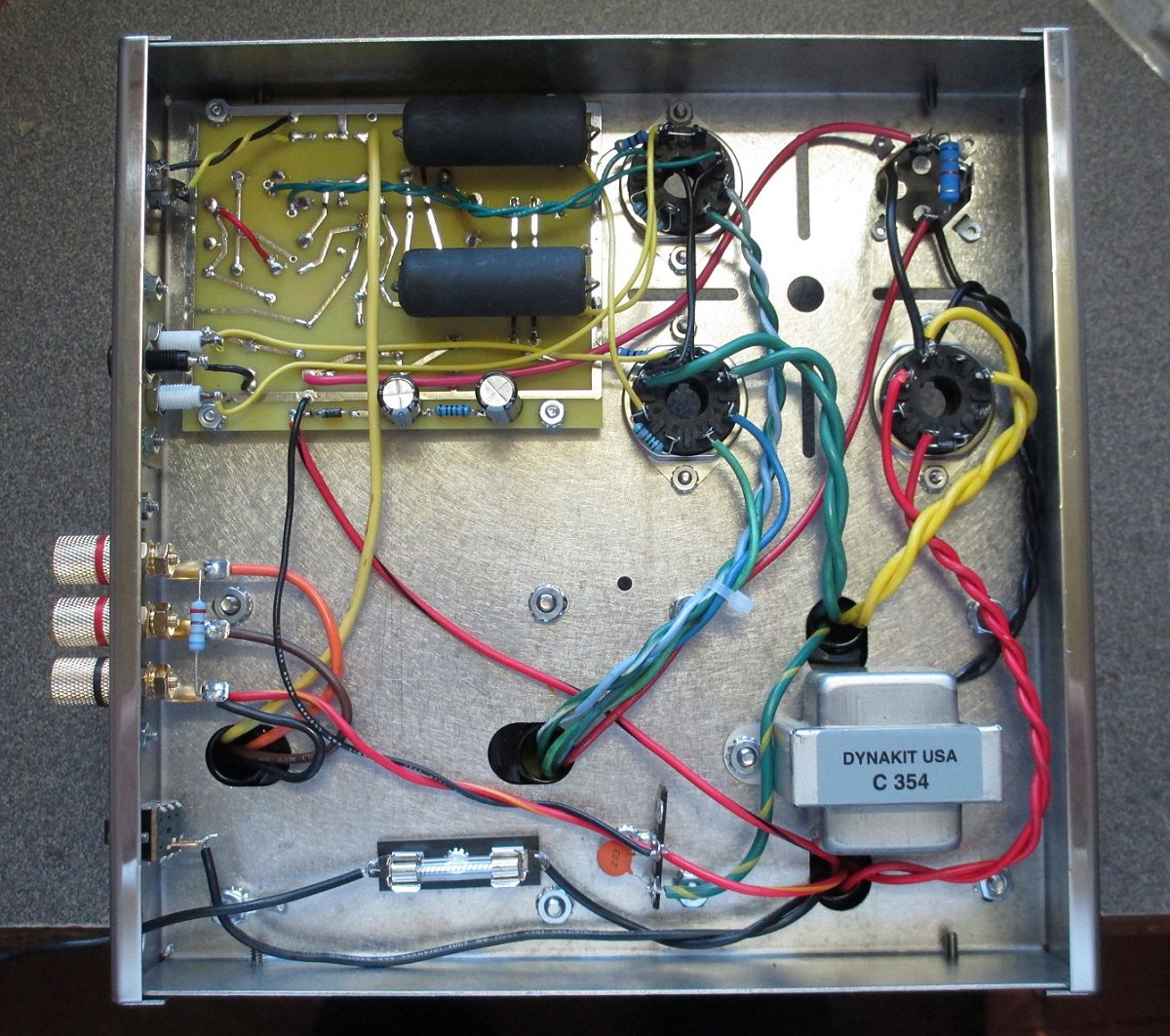
    I'll try to post a pic later when I get home. I did take some more readings last night and I'll post them below, but first I'll offer more details that I omitted in my frustration last night.

    First, at this point we're dealing with a mark III in a Mark II chassis. This began as a resto project but I found just about every part was failed or out of spec, so I decided to replace everything. Waste of money maybe but whatever.
    Second, I've built and restored several amps with success, but this is a hobby. I'm no pro and unfortunately I don't have any diagnostic tools beyond a DMM.
    This issue of AC where it shouldn't be existed with the original transformer (I assumed it to have developed a short so I replaced it), and now with a brand new one.
    The amp worked (poorly) before I started any restoration work.

    I'll preface the below with the fact that nothing other than transformer leads are connected to the rectifier tube socket.
    Pins 6-2, 6-8, 4-2, 4-8 - all read infinite.

    All secondary windings to primary windings, infinite.
    High voltage windings to each other, 81ohm.
    5v windings to each other, 0hm.

    High voltage seems low, only 400vac on pins 4-6.
    B+ through a solid state rectifier is only 420vdc.

    DMM leads on pins 8&2 read 5.3vac.
    DMM leads on chassis and either pin 8 or 2 - 163vac (sorry, I transposed digits in my original post).

    Bias supply is also high, about 80vac (selenium is gone, 1n4007 in it's place). Getting about -77vdc on the other side of the diode.

    Here's where it really gets weird.
    After taking the readings above, I removed the 5V leads from the rectifier socket, wrapped them up and tied them away, and again with a solid state rectifier inserted, I'm seeing 420vdc on pin 8, AND about 200vac.
    One bad transformer is one thing. Hell, the original was dated 1956. But two? I don't know. Really at a loss with this thing.

    Thanks for the ideas so far fellas.
    avatar
    drafalske


    Posts : 15
    Join date : 2015-10-11

    Dynaco MKII Troubleshooting Empty Re: Dynaco MKII Troubleshooting

    Post by drafalske Fri Dec 14, 2018 3:14 pm

    Here's a fairly hi res pic of the guts of this silly thing.


    Dynaco MKII Troubleshooting Dynaco12
    WLT
    WLT


    Posts : 186
    Join date : 2013-07-13
    Location : Rochester NY

    Dynaco MKII Troubleshooting Empty Re: Dynaco MKII Troubleshooting

    Post by WLT Sat Dec 15, 2018 11:12 am

    Thanks for the photo. I think I see the problem. Look carefully at how you wired the red leads to the rectifier socket. It appears the notch is facing the filter caps. If so you have one of the red leads connected to pin 6 but the other to pin 8! - not 4 .

    Please double check. I hope you kept the original transformer. They are actually pretty sturdy. Let us know what you find.
    avatar
    drafalske


    Posts : 15
    Join date : 2015-10-11

    Dynaco MKII Troubleshooting Empty Re: Dynaco MKII Troubleshooting

    Post by drafalske Sat Dec 15, 2018 12:00 pm

    Yeah, I did keep the old transformers. No idea what I'll do with them.
    Here's a nice closeup of the rectifier socket. Looks right to me (I've got the "yellow sheet mod" incorporated here).

    Dynaco MKII Troubleshooting Unname10
    WLT
    WLT


    Posts : 186
    Join date : 2013-07-13
    Location : Rochester NY

    Dynaco MKII Troubleshooting Empty Re: Dynaco MKII Troubleshooting

    Post by WLT Sat Dec 15, 2018 1:12 pm

    I see the diodes better now. The bias voltage is high. The B+ is low. This is weird.

    Overall you have a nice rebuild. May sound dumb but lift the red leads and then test for the bias voltage again. Then put the red leads back on and lift the bias lead and see what happens. Somehow the AC will disappear and whatever was not connected is part of the problem.

    I see you added a small cap on the 6 volt winding like the MK III have, No cap for he MK IIs. Try a jumper across it. Something will show up somehow. Sorry but I am running out of ideas as well.
    avatar
    drafalske


    Posts : 15
    Join date : 2015-10-11

    Dynaco MKII Troubleshooting Empty Re: Dynaco MKII Troubleshooting

    Post by drafalske Sat Dec 15, 2018 3:28 pm

    I've done a bit more troubleshooting and I think I've found something interesting.
    I lifted the high voltage leads and the bias supply. High voltage is showing a more normal 439vac. Bias supply is showing 58vac.
    With the high voltage leads lifted, I used a test jumper to reconnect the bias lead. Still getting 58vac on the cathode side, but -80vdc on the anode side.
    How is that possible?

    I also pulled the rectifier tube socket out of the chassis and reconnected the leads to it. Voltage went back down to 400vac. For the hell of it, I moved the leads to their normal pins (bypassing those two diodes). Back up to 439vc. I plugged in my SS rectifier (which is simply a homemade device consisting of a couple diodes soldered into a tube base - it works in other amps). 400vac on pins 4&6, 400vdc B+ AND 179vac on pin 8.

    I don't know why, but the weirdness seems centered around the 1N4007's.

    You didnt suggest this, but I've also been shining all around the inside of this thing with an extremely bright flashlight, looking for anything out of place, a stray piece of debris, solder drip. Anything that could cause a short. Not finding anything.


    WLT
    WLT


    Posts : 186
    Join date : 2013-07-13
    Location : Rochester NY

    Dynaco MKII Troubleshooting Empty Re: Dynaco MKII Troubleshooting

    Post by WLT Sat Dec 15, 2018 4:48 pm

    I just pulled out my spare original stock MK III and did some of the same measurements you did. Same power transformer you have. All tubes in and connected. Warmed up for a few minutes but not long.

    The Bias connection is 56 VAC to the cathode and -75 VDC at the anode. That is 1.4 x the AC voltage. That is the correct drop for a diode and the difference between our transformers is not that much. Yours is just a little higher. My amps uses the 2 - 50 mF caps not 2 - 100 uF so that may be one reason for several volts different.

    Red to red measures 77 ohms so it is a little different but not much. From pin 4 to grnd is 403 VAC and from pin 6 to grnd is 405 VAC. B+ is 465 VDC. I measured the AC to grnd on pin 2 and it is very low. Not 175 + VAC

    I noticed you connected the red/yellow transformer lead to a terminal and then use the chassis as ground. My amp has a wire that connected the R/Y terminal to the output transformer ground connection. A redundant transformer ground reference makes sense. Try a temporary jumper from the R/Y terminal to another good ground location.
    avatar
    drafalske


    Posts : 15
    Join date : 2015-10-11

    Dynaco MKII Troubleshooting Empty Re: Dynaco MKII Troubleshooting

    Post by drafalske Sun Dec 16, 2018 10:07 am

    Well. I've tried everything I can think of. Even with all the center taps lifted and checking this way and that, I'm still seeing high AC on pin 8 of the rectifier socket. I can't think of any other way for it to be there other than the transformer being shorted somewhere.
    I'm just gonna bag this thing and maybe do a scratch build from a kit at a later date.
    Thanks for going out of your way to help. I really appreciate it.

    avatar
    drafalske


    Posts : 15
    Join date : 2015-10-11

    Dynaco MKII Troubleshooting Empty Re: Dynaco MKII Troubleshooting

    Post by drafalske Mon Dec 17, 2018 1:53 pm

    I made one last ditch effort on this thing just now.  I removed the power transformer from the chassis, lifted all connections, and hooked everything up on my bench outside the amplifier chassis.  Wanted to remove all other variables.
    Anyway, still getting 136vac at pin 2.  Point of reference is the center tap.  
    This transformer is shorted out, isn't it?
    WLT
    WLT


    Posts : 186
    Join date : 2013-07-13
    Location : Rochester NY

    Dynaco MKII Troubleshooting Empty Re: Dynaco MKII Troubleshooting

    Post by WLT Mon Dec 17, 2018 3:49 pm

    It sure sounds like it. You actually removed the rectifier socket as well? Did you try to replace the socket during this testing process. Not sure how that could effect it but you seem to have tried everything else.

    You should be able to measure a low resistance reading from the 117 V winding to the 5 volt winding if it is shorted. The numbers (house voltage + 5 volt winding) still do not add up to 136 VAC though.

    It is hard to image that an older transformer and a replacement newer one both had the same problem.
    avatar
    drafalske


    Posts : 15
    Join date : 2015-10-11

    Dynaco MKII Troubleshooting Empty Re: Dynaco MKII Troubleshooting

    Post by drafalske Tue Dec 18, 2018 2:35 pm

    It is hard to image that an older transformer and a replacement newer one both had the same problem.

    Yeah, that's what is so confounding about this. One bad transformer? OK. It was old. But a second, brand new one, not only bad out of the box but with the same failure mode? I'm having a hard time buying it as well.

    To answer your question about the tube socket, yes it was a new replacement but I left it in the chassis and used another new one I had laying around for testing outside the chassis.
    I also ran the same test on the old transformer. Voltages are a little different but exact same failure mode.

    What I think is actually happening is the AC is somehow bleeding back through the center tap. That's been the point of reference all along so I think that's where the problem is. I can't just leave it disconnected can I?

    I don't know. Still wish there was a "smoking gun" (instead of a smoking filter cap!).

    Thanks again for all your help. I'm going to seek a RMA for this transformer, but I'll be shelving this project for the time being.
    WLT
    WLT


    Posts : 186
    Join date : 2013-07-13
    Location : Rochester NY

    Dynaco MKII Troubleshooting Empty Re: Dynaco MKII Troubleshooting

    Post by WLT Tue Dec 18, 2018 2:55 pm

    I can't just leave it disconnected can I?

    No. The high voltage DC is referenced to ground via a full wave center tap arrangement using the rectifier. Then the audio circuit is referenced to that ground point utilizing that high voltage.

    Just give the issue a break for a while. Sometimes a little time off pays dividends when you take it up again. Good luck and I would love to hear the final outcome once resolved.
    Roy Mottram
    Roy Mottram
    Admin


    Posts : 1839
    Join date : 2008-11-30

    Dynaco MKII Troubleshooting Empty Re: Dynaco MKII Troubleshooting

    Post by Roy Mottram Tue Dec 18, 2018 6:43 pm

    drafalski
    compare to my photo of a MK3 wiring below, but you don't have the 5v filament wires connected (the yellow wires). And where is the B+ to the quad cap??
    If that doesn't fix it, from your symptoms, I think you have a shorted rectifier tube.   Try a new rectifier, or add two more diodes to the rectifier socket (for SS rectification)
    (or swap the wire locations since you already have two diodes there)

    Dynaco MKII Troubleshooting MK3-14
    WLT
    WLT


    Posts : 186
    Join date : 2013-07-13
    Location : Rochester NY

    Dynaco MKII Troubleshooting Empty Re: Dynaco MKII Troubleshooting

    Post by WLT Tue Dec 18, 2018 8:49 pm

    Drafalski - Your comment about the problem revolving around the center tap ground got me thinking. What if the Red/Black and the Red/Yellow wires were actually installed incorrectly (reversed) inside the transformer. The bias wire would be connected as the ground and the center tap ground wire is now the bias feed. The bias supply would still have the same voltage because they reference each other. The Red/Red resistance and overall AC voltage would be fine but the high voltage DC to ground would be lower due to the center tap not being in the center of the red/red winding. your high voltage winding AC reference to ground would be offset because it is a reference to the bias tap not the center tap. That offset could explain some AC being in the wrong place downstream. When I measured mine both red lead to ground AC were pretty close. I reread your comments and I did not see were you listed your results for those tests.

    One way to check is to remove all transformer connections and then measure resistance from both red leads to red/yellow. They should be (almost) the same reading. Then measure from each red lead to red/black. One should be much different than the other. If these readings are reversed I think you found the problem.

    I hope it is that simple. Connect the red/black as the ground and the red/yellow as the bias supply connection.
    avatar
    drafalske


    Posts : 15
    Join date : 2015-10-11

    Dynaco MKII Troubleshooting Empty Re: Dynaco MKII Troubleshooting

    Post by drafalske Wed Dec 19, 2018 11:37 am

    Tubes4Hifi - Appreciate you looking and the advice.  I wish it was that simple.  I've already tried multiple known good rectifiers (tube and solid state both), all with the same results.  The yellow wires were disconnected because at the time I took that photo I was testing with a solid state rectifier installed and they weren't needed.  The connection B+ to the quad cap is also lifted because that quad cap is fried.  I have a replacement on the way, but I won't install it until I'm seeing absolutely no AC current on pin 8.     

    WLT - I've done so much poking around in this thing that I can't remember if I tested that or what the results were.  I'll have a look when I get home from work.

    One thing I haven't asked, and readings are showing the connections are solid, but what about a grounding issue?  This is an early MKII chassis so it's had 60+ years to get grungy.  I've heard these are cadmium plated - is it safe to take a little emery cloth to the ground connections to make sure they're 100% clean?


    Last edited by drafalske on Wed Dec 19, 2018 4:57 pm; edited 1 time in total
    WLT
    WLT


    Posts : 186
    Join date : 2013-07-13
    Location : Rochester NY

    Dynaco MKII Troubleshooting Empty Re: Dynaco MKII Troubleshooting

    Post by WLT Wed Dec 19, 2018 12:48 pm

    Yes - A little clean up of the ground connections is reasonable. I think you removed much of the connections anyway when you tested outside the amp. The Cadmium usually makes a pretty good ground.

    I am very interested in the resistance testing I mentioned when you get home from work.
    avatar
    drafalske


    Posts : 15
    Join date : 2015-10-11

    Dynaco MKII Troubleshooting Empty Re: Dynaco MKII Troubleshooting

    Post by drafalske Wed Dec 19, 2018 1:38 pm

    I think you removed much of the connections anyway when you tested outside the amp.

    True, and it made no difference. Given that, I think I'll forego cleaning up the grounds for now.

    Here are he voltage readings:

    R - R = 86
    R1 - RY = 42
    R2 - RY = 46
    R1 - RB = 50
    R2 - RB = 36
    RY - RB = 6

    I don't know, everything looks close enough to me. Again though, I don't consider myself an expert.
    WLT
    WLT


    Posts : 186
    Join date : 2013-07-13
    Location : Rochester NY

    Dynaco MKII Troubleshooting Empty Re: Dynaco MKII Troubleshooting

    Post by WLT Wed Dec 19, 2018 4:53 pm

    The numbers are not perfect but do tend to indicate that the red/yellow tap is near the center of the red/red winding like it should be. The red/black tap is closer to the R2 end which is reasonable.

    I am sorry but am no help for you at this point.
    avatar
    drafalske


    Posts : 15
    Join date : 2015-10-11

    Dynaco MKII Troubleshooting Empty Re: Dynaco MKII Troubleshooting

    Post by drafalske Wed Dec 19, 2018 4:56 pm

    Don't be sorry at all! I appreciate all your help. I'll revisit this thread when/if I ever get this thing up and running, but I'm shelving it for now.
    avatar
    drafalske


    Posts : 15
    Join date : 2015-10-11

    Dynaco MKII Troubleshooting Empty Re: Dynaco MKII Troubleshooting

    Post by drafalske Tue Feb 05, 2019 9:58 am

    Well. I figured it out.
    The issue was not the AC voltage on pin 8 at the rectifier. That's still there and none of my other tube amps do it, but it doesn't seem to be causing any harm so I'm just gonna call it an anomaly and move on. No, the issue was the surge of nearly 600vDC at powerup that was wiping out the 525vDC rated can cap.

    I'm a little ashamed I didn't test for this straightaway since it's so obvious now, but then again I'm no pro. I learned the hard way this time but it's experience I won't forget and can apply in the future, so all isn't lost I guess.

    Anyway, I took some 450V/80uf caps I had laying around and set them up in series just to test the theory, and voila - I have a working amp. I know Dynakit sells a can rated for a 600vDc surge, but I'm leaning more toward the SDS Labs cap board as my permanent solution. I kind of like the overkill it offers in regard to voltage rating.

    Only issue remaining is B+ is a little higher than I'd like. With the KT-88's biased at 50mA, I'm seeing 550vDC to the output transformer center tap, and about 425vDC to the driver board. This is with a GZ34 rectifier. I may try a 5U4 and see if it will drop a bit.

    I want to thank everyone again for the help. We were looking in the wrong direction but it still means a lot to me.

    Sponsored content


    Dynaco MKII Troubleshooting Empty Re: Dynaco MKII Troubleshooting

    Post by Sponsored content


      Current date/time is Thu May 02, 2024 8:35 pm