Hello forum, please call me Tim as it is what everyone else does. I am rather new to this forum, have been lurking for a while though. I am embarking on a slow journey of MK II restorations. I hope I can be helpful to those here and tha this project will be helpful as well.
I hope I am posting this in the right section otherwise please move this for me or let me know where I should post to.
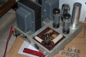
I have been a Dynaco fan since 1969 and decided that the Dynaco would be my ultimate system, and over the years I have collected a lot of vintage audio gear, but not what I really wanted. Retirement helps one focus on the "IT'S Time" aspect, so I bought a pair of MK II's of Ebay to fiddle with. I did worry about the transformers and took a chance on these. Both units have many many issues, but the Iron is good. With that being the case, I now begin the journey of restoring these pups to workable condition.
I go slow, getting old and eyes not what they used to be, on top of that I am in the middle of a move, unpacking state finally, and getting my workbench put together.
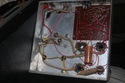
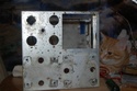
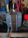
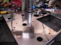
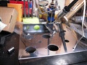
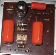
Anxious to know what is ahead I opened each up on the kitchen table to get a feel of the conditions inside. So far this is what I have found, Unit #1. Kit build, fairly decent work over all. There is no 25 pF capacitor in this unit (6AN8 pins 2&6), there is no 12 ohm cathode resistor (EL34 pins 1& pins go directly to ground.
As I look over the manual I notice that the image of pictorial 2 actually shows this way of wiring yet the schematic shows them 12 ohm.
As I proceed I like to gather information that gives me a feel for what the amplifier has been through, the history that can be ascertained. I get the impression that this unit was wired by pictorial rather than documentation.
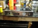
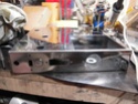
Both transformers DC test good, the power transformer no load is 416-0-418, 6.38 and 5.26 @ 120 Input. The output transformer shows a normal output on 4,8, and 16 ohms with an input of 20 Hz to 20 Khz (HP 400C)input, testing each tap to the center tap. I know that the real test will be with high voltage and Under load.
This seems to be the gentler of the two units and I will refer to this as Unit #1.
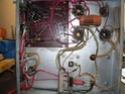
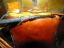
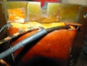
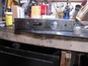
The 2nd unit has seen a much harder life, right from the beginning. Again this unit does not have the 25 pF capacitor on the 6AN8, and does have the 12 ohm resistor from the cathodes to ground. On my visual examination I began to find poor solder connections, cold joints. With a little wiggle of the component or wire, the joint would break away and the solder would crumble. Again the transformers tested the same as the first unit, so I will proceed forward using the original transformers.
I was glad to find a post by Bob Latino of the letter Dynaco issued in 1957 for the upgrade to the Mark III circuit. During this restoration my plan is to implement this on both units.
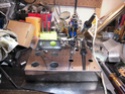
I did test the quad capacitor on both, and as expected one section is shorting. I believe that the quad caps are original in both units, manufacture of Astron. Unit #1 has Ceracaps on the PCB, unit #2has the same except on of the .25 uF has been replaced with a Astron. The tube socket on unit #2 PCB has been replaced with a black body (taller) socket, and the workmanship is rather dismal. I will have to do a lot of trace repairs as well here.
I will get the images I have so far resized and set up ma hosting account as well for the images.
Tim
I hope I am posting this in the right section otherwise please move this for me or let me know where I should post to.
I have been a Dynaco fan since 1969 and decided that the Dynaco would be my ultimate system, and over the years I have collected a lot of vintage audio gear, but not what I really wanted. Retirement helps one focus on the "IT'S Time" aspect, so I bought a pair of MK II's of Ebay to fiddle with. I did worry about the transformers and took a chance on these. Both units have many many issues, but the Iron is good. With that being the case, I now begin the journey of restoring these pups to workable condition.
I go slow, getting old and eyes not what they used to be, on top of that I am in the middle of a move, unpacking state finally, and getting my workbench put together.
Anxious to know what is ahead I opened each up on the kitchen table to get a feel of the conditions inside. So far this is what I have found, Unit #1. Kit build, fairly decent work over all. There is no 25 pF capacitor in this unit (6AN8 pins 2&6), there is no 12 ohm cathode resistor (EL34 pins 1&
As I look over the manual I notice that the image of pictorial 2 actually shows this way of wiring yet the schematic shows them 12 ohm.
As I proceed I like to gather information that gives me a feel for what the amplifier has been through, the history that can be ascertained. I get the impression that this unit was wired by pictorial rather than documentation.
Both transformers DC test good, the power transformer no load is 416-0-418, 6.38 and 5.26 @ 120 Input. The output transformer shows a normal output on 4,8, and 16 ohms with an input of 20 Hz to 20 Khz (HP 400C)input, testing each tap to the center tap. I know that the real test will be with high voltage and Under load.
This seems to be the gentler of the two units and I will refer to this as Unit #1.
The 2nd unit has seen a much harder life, right from the beginning. Again this unit does not have the 25 pF capacitor on the 6AN8, and does have the 12 ohm resistor from the cathodes to ground. On my visual examination I began to find poor solder connections, cold joints. With a little wiggle of the component or wire, the joint would break away and the solder would crumble. Again the transformers tested the same as the first unit, so I will proceed forward using the original transformers.
I was glad to find a post by Bob Latino of the letter Dynaco issued in 1957 for the upgrade to the Mark III circuit. During this restoration my plan is to implement this on both units.
I did test the quad capacitor on both, and as expected one section is shorting. I believe that the quad caps are original in both units, manufacture of Astron. Unit #1 has Ceracaps on the PCB, unit #2has the same except on of the .25 uF has been replaced with a Astron. The tube socket on unit #2 PCB has been replaced with a black body (taller) socket, and the workmanship is rather dismal. I will have to do a lot of trace repairs as well here.
I will get the images I have so far resized and set up ma hosting account as well for the images.
Tim
 peterh