The Dynaco Tube Audio Forum

Would you like to react to this message? Create an account in a few clicks or log in to continue.
The Dynaco Tube Audio Forum

Dedicated to the restoration and preservation of all original Dynaco tube audio equipment - Customer support for Tubes4hifi VTA tube amp and preamp kits and all Dynakitparts.com products


+9
Dave_in_Va
10-E-C
pedrocols
IEales
baddog1946
KenGaler
audiobill
Bob Latino
Dale Stevens
13 posters

    M-125 Build

    KenGaler
    KenGaler


    Posts : 76
    Join date : 2019-10-11

    M-125 Build Empty M-125 Build

    Post by KenGaler Fri Oct 18, 2019 12:41 pm

    Hi All,

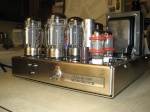
    Just moved to NC from CT and finally got around to setting up my stereo system.  It has a Krell KAV-300i amp and I have no real complaints other than it looks kinda boring.  A friend has a bi-amped McIntosh system that looks and sounds fantastic so I checked out the prices to find out that I'll need my own oil field to afford it.  After a bit of searching I found tubes4hifi and wound up getting two M-125 kits.  Thanks Bob.

    I'm an EE and own a contract engineering company but have very little experience with tubes other than with HF transmitters 40 years ago.  This should be a fun learning experience.  I don't remember the last time I had to be concerned about 500VDC while probing around.  

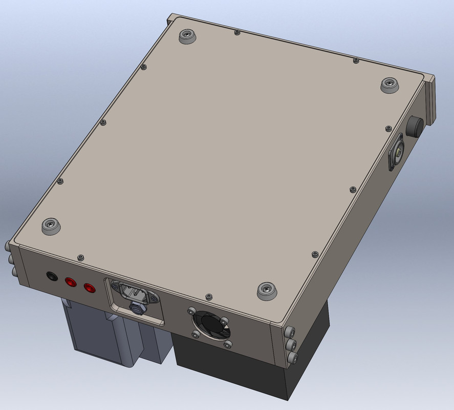
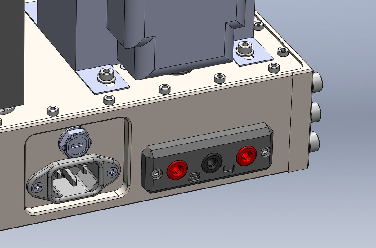
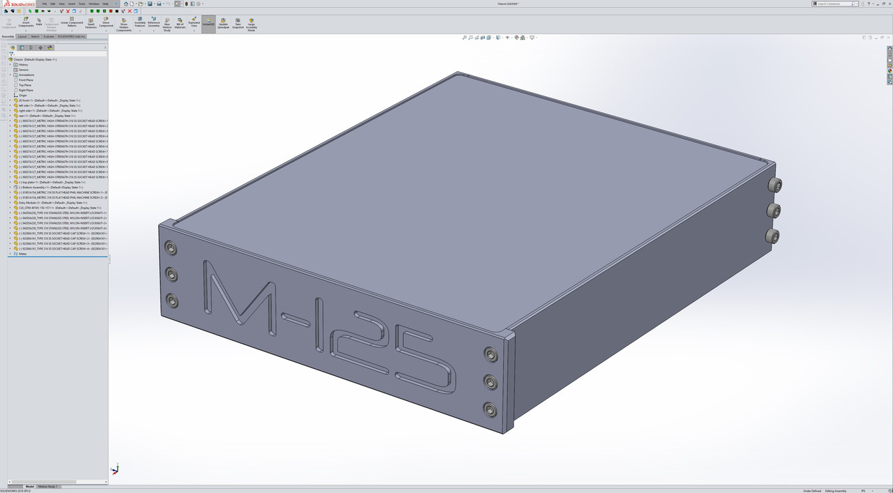
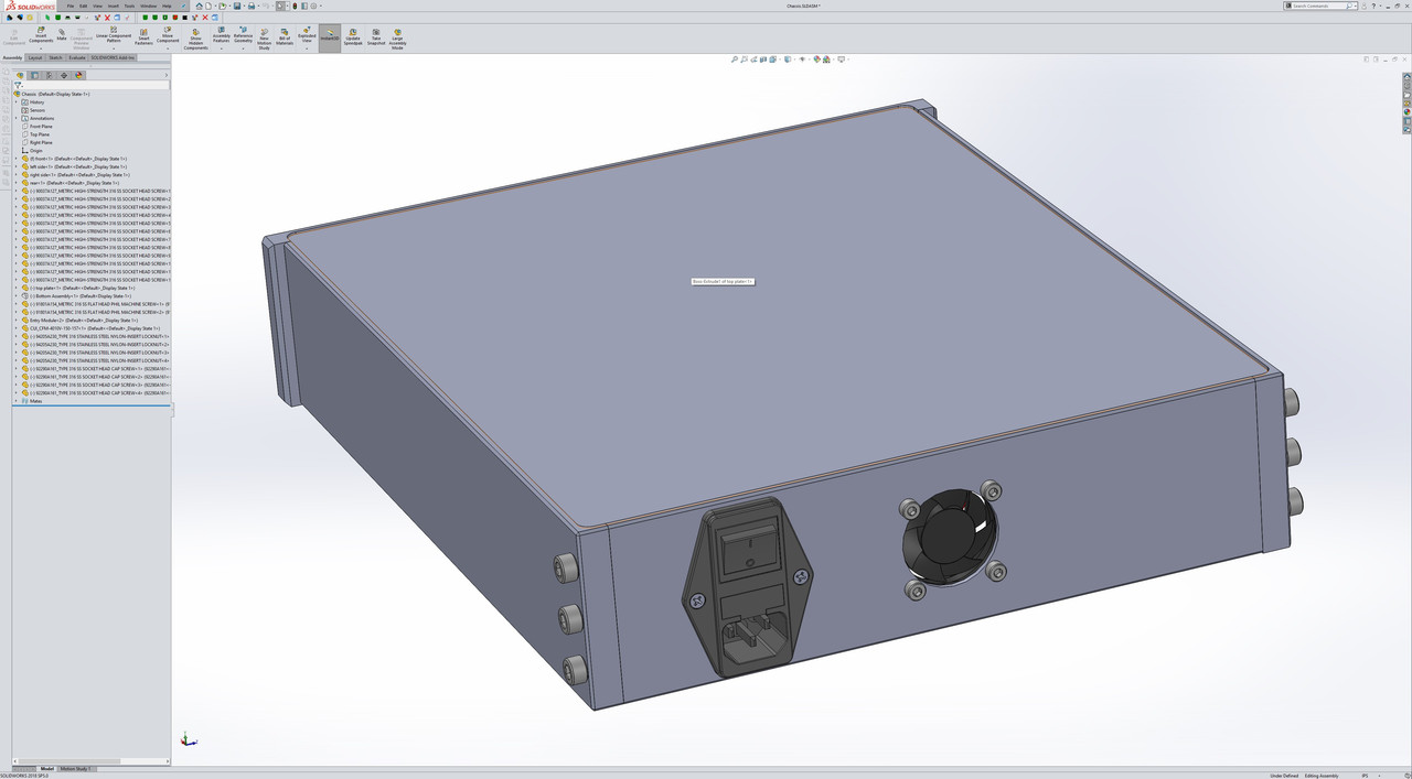
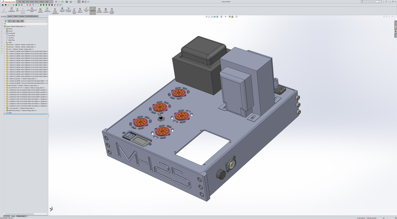
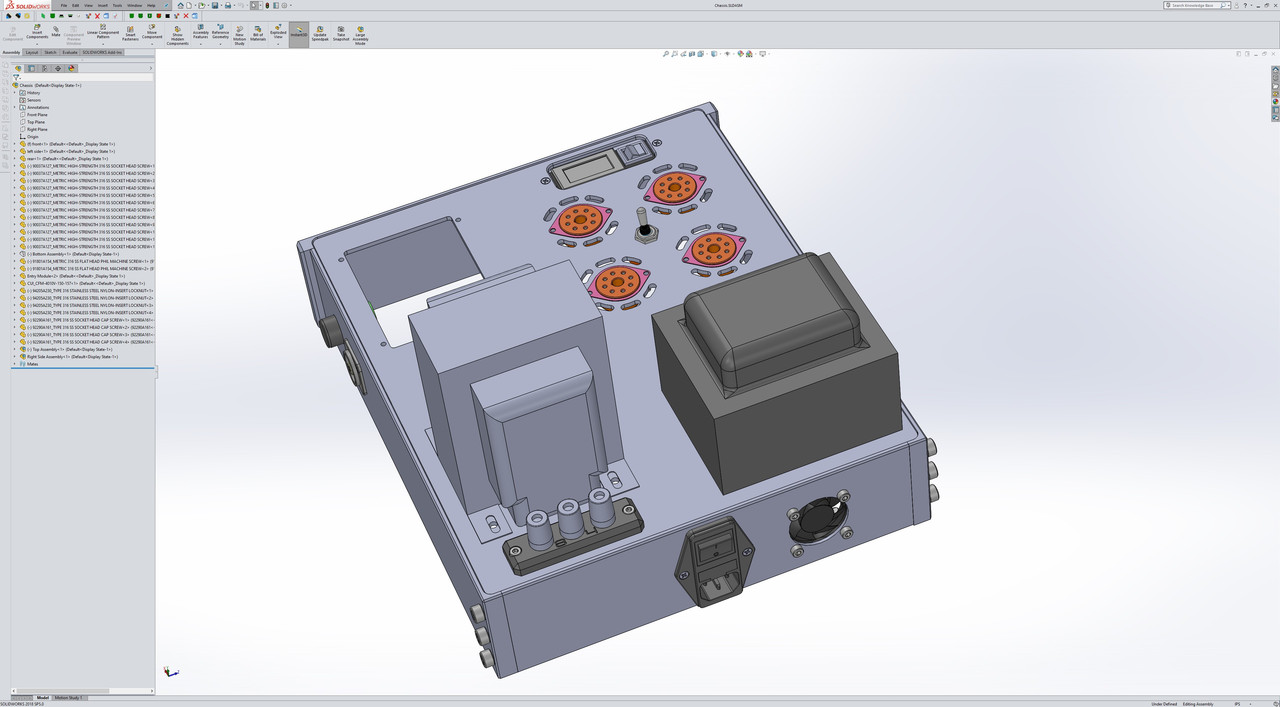
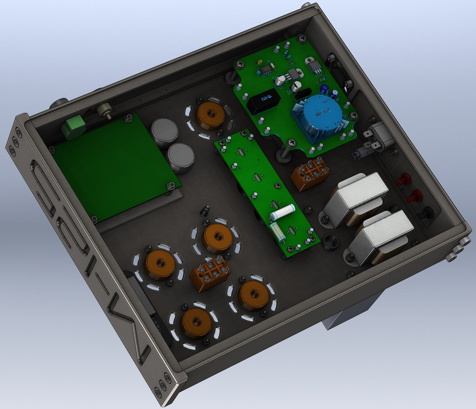
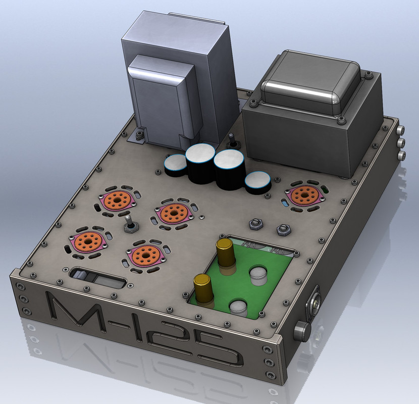
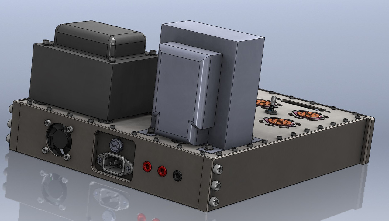
    The kit looks great but I am going to make some modifications only because I can't help it.  Mostly cosmetic but I am going to add an input attenuator and change the B+ supply filter.  In case anyone is interested I'll post pics here as it goes.  I'll start with a couple screen shots of the preliminary chassis model.  I'm planning to keep with the SS theme and make it out of 316 stainless.  

    M-125 Build Early-Model-Front


    M-125 Build Early-Model-Rear
    avatar
    Dale Stevens


    Posts : 201
    Join date : 2014-07-06
    Age : 75
    Location : Loris, SC

    M-125 Build Empty Re: M-125 Build

    Post by Dale Stevens Fri Oct 18, 2019 5:01 pm

    Welcome Ken. I'm close by near Myrtle Beach. Great support here. Remember that SEARCH is very handy dandy. I have the VTA ST 120 in front of Khorns. Looks like one more super project . Yes, post all your build. Dale
    Bob Latino
    Bob Latino
    Admin


    Posts : 3263
    Join date : 2008-11-26
    Location : Massachusetts

    M-125 Build Empty Re: M-125 Build

    Post by Bob Latino Sun Oct 20, 2019 10:41 am

    Hi Ken,

    Keep us informed of your progress and post pictures along the way as you go through the build ..

    Bob
    KenGaler
    KenGaler


    Posts : 76
    Join date : 2019-10-11

    M-125 Build Empty Re: M-125 Build

    Post by KenGaler Wed Oct 23, 2019 4:36 pm

    More Tweaks.  Added a small 2VDC panel meter to avoid the walk into the next room to get a multimeter  :-)

    M-125 Build Model-Front-2

    M-125 Build Model-Rear-2
    avatar
    audiobill


    Posts : 425
    Join date : 2014-03-13
    Location : Albany, NY

    M-125 Build Empty Re: M-125 Build

    Post by audiobill Wed Oct 23, 2019 7:08 pm

    Be sure to leave room for the time delay relay board,or autobias, or both if you choose to add them.
    KenGaler
    KenGaler


    Posts : 76
    Join date : 2019-10-11

    M-125 Build Empty Re: M-125 Build

    Post by KenGaler Thu Oct 24, 2019 12:46 pm

    I plan on using the 5AR4 for the rectifier but I'm undecided about the auto bias. I wonder if it's really a problem that needs solving. I don't mind adjusting a pot once in a while. (It's worth noting that trimmer pots are normally lifetime rated for 200 turns but the only time I've actually seen one fail was in a prototype that was turned a lot during development.) The solid-state auto-bias circuit goes against the whole tube old-school thing. I did use a modern voltmeter but only because I wasn't able to find an analog voltmeter that was small, accurate, and looks old school.

    avatar
    audiobill


    Posts : 425
    Join date : 2014-03-13
    Location : Albany, NY

    M-125 Build Empty Re: M-125 Build

    Post by audiobill Fri Oct 25, 2019 6:40 am

    You may wish to think twice about using the 5AR4 in lieu of the WZ68 solid state rectifier. While the 5AR4 will work fine, the WZ68 is capable of delivering twice the current to KT120s.
    KenGaler
    KenGaler


    Posts : 76
    Join date : 2019-10-11

    M-125 Build Empty Re: M-125 Build

    Post by KenGaler Fri Oct 25, 2019 11:35 am

    I am tempted to use that WZ68 for reliability. It does look good also..... OK, I just bought them.

    Do I understand this correctly? When powering up cold there is no load on the B+ until the power tubes warmup and this causes the voltage to peak charge to too high of a value. The delay relay holds off the B+ for a time to allow for the tubes to come on.


    baddog1946
    baddog1946


    Posts : 319
    Join date : 2010-02-03
    Location : Costa Rica

    M-125 Build Empty New M-125 project

    Post by baddog1946 Sun Nov 03, 2019 7:59 am

    hi all:
    Great project, should look spectacular in real life photos.

    Where is the meter you mention going to be located? Do you have a sketch up of that yet. Very thoughtful layout so far, What are the chassis dimensions?
    I am looking at this and the parts lists etc. are too small to read. As a DIY addict I am always interested in suppliers etc. At some point I for one would be happy to see this part of your build info.
    My thoughts on the auto bias are they assist in the output tubes life, "tube purism " be damned. The delay board is also a must have tube lifesaver. IMHO.
    Both appear to be bulletproof so far in my amps.

    What is the jack type exactly beside the volume control? My final question is where are you having this S.S. chassis made? It looks very expensive but very cool.
    .................................the bad dog

    P.S.
    I live in a very hazardous electrical environment in Costa Rica and I cannot stress enough the use of a surge protection device when using the WZ- 68's as they seem particularly vulnerable to this problem by burning out the diodes. I also had a couple with the resistor burning out. I now use them with carefully drilled vent holes in the copper casing for better cooling. I have a cemetery collection of at least 10 fried WZ-68's from this issue. I have even rebuilt several with bigger diodes and managed to burn a couple of those out too during tropical storms we get here regularly. The good news is they are cheap.
    baddog1946
    baddog1946


    Posts : 319
    Join date : 2010-02-03
    Location : Costa Rica

    M-125 Build Empty Re: M-125 Build

    Post by baddog1946 Sun Nov 03, 2019 8:55 am

    OK now I see the meter is right on the top........................... damn! alzheimers light.
    KenGaler
    KenGaler


    Posts : 76
    Join date : 2019-10-11

    M-125 Build Empty Re: M-125 Build

    Post by KenGaler Sun Nov 03, 2019 12:25 pm

    Any and all ideas welcome, thank you.

    This is the RCA plug. Not that there is anything wrong with the one that comes ion the kit. I just think this looks a bit better. https://amzn.com/B003VW0IWE

    This is the 2VDC meter. https://is.gd/sVzsWC

    I'm adding the input attenuator only because I'm concerned about the MAX output and I may wish I had it. My present amp is 150w/ch and the speakers are way too loud at about 1/4 the way up. The volume is controlled by a tablet and it's just a matter of time before it comes up mistakenly too high and blows up a speaker.

    Good thought about the surge protection, I'll add a MOV. My VAC is here is a very consistent 121V.

    I'm just about done with the mech design, close enough to add the pics. The SS machining will probably be a lot more than I bargained for when this started but now I'm committed. For me this is a mental-health project and lets me think about something more relaxing than customer projects.
    KenGaler
    KenGaler


    Posts : 76
    Join date : 2019-10-11

    M-125 Build Empty Re: M-125 Build

    Post by KenGaler Sun Nov 03, 2019 12:31 pm

    M-125 Build Model-bottom-3

    M-125 Build Model-Front-3

    M-125 Build Model-Rear-3
    KenGaler
    KenGaler


    Posts : 76
    Join date : 2019-10-11

    M-125 Build Empty Re: M-125 Build

    Post by KenGaler Sun Nov 03, 2019 12:57 pm

    The center PCB is the B+ filter.  Because of its shape it made sense to swap the transformer positions.  Now the B+ flows from the power transformer, through the filter board and right to the output transformer.  The PCB under other PCB is a regulator/delay board.  I would have used Bobs delay board but I also needed to make +5V for the meter and an adjustable 12VDC for the fan.  That blue transformer is a toroidal so I'm hoping it doesn't cause any hum.  There isn't a lot of current here anyway.  

    I plan on either glass or plexy to cover the driver PCB.

    I might remove the milled "M-125" from the front because I don't like the font and haven't found an engraving font I do like.  Maybe an embedded glass front with a label behind it.


    Last edited by KenGaler on Sun Nov 03, 2019 1:58 pm; edited 1 time in total
    KenGaler
    KenGaler


    Posts : 76
    Join date : 2019-10-11

    M-125 Build Empty Re: M-125 Build

    Post by KenGaler Sun Nov 03, 2019 2:13 pm

    Do you think a stepped attenuator will be be a problem? Are you concerned about added noise?

    I am planning on an external power box with a bucking transformer and a GFI socket. I'm thinking -5VAC is about right. I like those volt meters better than the one I found. I may change to them.

    We are definitively thinking the same way with the grounding. All the grounds connect to the same point on the chassis somewhere near the middle of the power tubes. No current at all in the chassis.

    baddog1946
    baddog1946


    Posts : 319
    Join date : 2010-02-03
    Location : Costa Rica

    M-125 Build Empty "M-125 Build"

    Post by baddog1946 Sun Nov 03, 2019 3:01 pm

    The top plate in your first sketchup drawing looked like it was fastened from underneath and was very clean looking. The second drawing has 40 screws to hold the top on and 8 more for the boards etc.

    IMHO it looks a bit busy and could be pain to clean and polish. Still it's a sweet mental health project you have there. I look forward to watching you ideas coming into being. What is the out of control cost of that chassis anyway if I may ask?

    It would also look very nice in black anodized aluminium with those S.S. machine screws.
    cheers.............
    IEales
    IEales


    Posts : 3
    Join date : 2019-03-16
    Location : Florence OR

    M-125 Build Empty Re: M-125 Build

    Post by IEales Sun Nov 03, 2019 3:05 pm

    KenGaler wrote:Do you think a stepped attenuator will be be a problem?
    I'd like that better than pots unless you want to gain match with a voltmeter on each adjustment.
    Non-detent pots w/o locks have a tendency to creep - dusting, inadvertent contact, etc.
    Detent pots rarely match so channel tracking is an issue.
    Stepped attenuators build up inductance with the resistor series - less so w SMD parts.
    Truly, if it was a set and forget, I'd add a turret and two R.
    M-125 Build Turret 
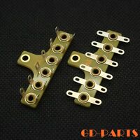
or similar - ebay search "turret board"


    KenGaler wrote:Are you concerned about added noise?
    Not unless the pot is defective. IMO, contacts are audible.
    Some outputs are DC coupled and over time the wiper / contact can be affected if there is any DC offset.
    Not usually a problem but it's the unusual that always throws the spanner.
    If I had the courage, I'd solder in my bottle rockets.

    KenGaler wrote:I am planning on an external power box with a bucking transformer and a GFI socket.  I'm thinking -5VAC is about right.
    Agreed. Our power is very stable but sometimes have 118-123 here, so I opted for the triple voltage.
    A must in some locations.


    KenGaler wrote:I like those volt meters better than the one I found
    If you buy them, get extras as they vary a bit. ± a count or two.
    Select the closest pair and return the rest.
    I swapped the lenses for a less garish look.
    KenGaler
    KenGaler


    Posts : 76
    Join date : 2019-10-11

    M-125 Build Empty Re: M-125 Build

    Post by KenGaler Sun Nov 03, 2019 3:36 pm

    I was trying to decide if that was too many screws.  It's way more than needed to keep the top plate from falling off.  I'm going for sort of an industrial look but maybe I went too far.  All those screws will be locktite'd in.  The bottom is the only part the will need to be removed.

    M-125 Build Model-Bottom-with-Cover
    baddog1946
    baddog1946


    Posts : 319
    Join date : 2010-02-03
    Location : Costa Rica

    M-125 Build Empty Re: M-125 Build

    Post by baddog1946 Sun Nov 03, 2019 4:04 pm

    I noticed there are only 2 bias pots. You will have to pay more attention to matching tubes, all 8 of them if you are biasing them in pairs. Roy's board has 4 way which I found very useful for tweaking. Are you using the VTA circuit but not the VTA board? Are you going to do the boards yourself?

    P.S. I would put a few vents in the bottom plate............................cheers
    avatar
    audiobill


    Posts : 425
    Join date : 2014-03-13
    Location : Albany, NY

    M-125 Build Empty Re: M-125 Build

    Post by audiobill Mon Nov 04, 2019 7:40 am

    baddog, there are two bias pots on the m125 board, and four for the ST70/ST120 board.
    KenGaler
    KenGaler


    Posts : 76
    Join date : 2019-10-11

    M-125 Build Empty Re: M-125 Build

    Post by KenGaler Mon Nov 04, 2019 6:14 pm

    In the power section, I'm thinking of changing to 4 individual 20 ohm cathode resistors.  Then changing the meters rocker switch to a 5 position rotary.  (Center position = OFF) This way I can I can measure each tubes bias individually to see if one is going bad.  Still keeping just two bias pots because if I go to 4 then I'll need two more of those coupling caps.


    The question is, does paralleling tubes require that they share a common cathode resistor?

    EDIT: After looking into it, it looks like I can use separate cathode resistors.
    KenGaler
    KenGaler


    Posts : 76
    Join date : 2019-10-11

    M-125 Build Empty Re: M-125 Build

    Post by KenGaler Tue Nov 05, 2019 2:02 pm

    IEales wrote:Unless you plan to use locking banana plugs, binding posts provide a better and more versatile contact.
    Some cables only come with spade option and will require adapters or re-termination.

    Good points!  I'd rather not have binding post hanging out the back while wiring and testing because they might get damaged.  That's why I had them located on top at first but ran out of room.  So, I'll change it to a plastic (3D printed) mount on the back.  This way, if I wind up wishing I used binding posts it's an easy plan B mod instead of machining a new back plate.  Thanks.


    M-125 Build Terminal-Detail
    pedrocols
    pedrocols


    Posts : 162
    Join date : 2014-11-24
    Location : Western MA

    M-125 Build Empty Re: M-125 Build

    Post by pedrocols Tue Nov 05, 2019 9:57 pm

    Not a fan of the banana plug only connector. You never know.
    KenGaler
    KenGaler


    Posts : 76
    Join date : 2019-10-11

    M-125 Build Empty Re: M-125 Build

    Post by KenGaler Wed Nov 06, 2019 10:10 am

    pedrocols wrote:Not a fan of the banana plug only connector.  You never know.

    I'm a little concerned also because I'm not sure how often they will be inadvertently yanked out. I'm not concerned about them electrically. They are good for about 10A. Worse case, at full power and a 4 ohm load the output current is about 4.5A.

    But, as I mentioned, if it becomes a problem I can just change to the binding posts.
    10-E-C
    10-E-C


    Posts : 267
    Join date : 2014-02-12
    Age : 70
    Location : upper east tn

    M-125 Build Empty Re: M-125 Build

    Post by 10-E-C Wed Nov 06, 2019 5:46 pm

    KenGaler wrote:
    pedrocols wrote:Not a fan of the banana plug only connector.  You never know.

    I'm a little concerned also because I'm not sure how often they will be inadvertently yanked out.  I'm not concerned about them electrically.  They are good for about 10A.  Worse case, at full power and a 4 ohm load the output current is about 4.5A.

    But, as I mentioned, if it becomes a problem I can just change to the binding posts.

    You can get locking banana plugs if you are worried they will be accidentally pulled out.
    KenGaler
    KenGaler


    Posts : 76
    Join date : 2019-10-11

    M-125 Build Empty Re: M-125 Build

    Post by KenGaler Thu Nov 07, 2019 10:11 am

    [/quote] You can get locking banana plugs if you are worried they will be accidentally pulled out.  [/quote]

    I've never heard of them.  I looked around and found "locking" banana plugs but they seem to be talking about the wire connection.  Do you have a link?  Tks

    Sponsored content


    M-125 Build Empty Re: M-125 Build

    Post by Sponsored content


      Current date/time is Wed May 01, 2024 5:57 pm