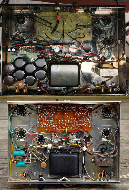
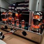
The amp was modded a couple of times before I got it.
I've un modded the head phone connections.
Issues with it included Lap Joint soldered that came undone.
Had the SDS board already installed. I found leaky caps,
removed board, installed all new caps.
Added back a good on/off switch.
It already had a 3 prong grounded power cord installed.
TEST: Clipping a two prong power cord to the two power conductors
of the three prong didn't make a difference.
Test: Swapping preamp tubes left to right didn't make a difference.
Test: Swapping power tubes left to right didn't make a difference.
Test: using different EL34s didn't make a difference.
Test: Using shorting plugs Increased 60 HZ hum and placed it in both channels.
Test: Pulling the left channel pre amp tube stopped the hum.
Therefore issue with the left channel presumably the old board.
Test: Installed another used board, yellow glass type board. didn't make a difference.
Test: repeated the same tests all over again, didn't make a difference.
60Hz hum still in the left channel.
Testing voltages and measuring components from side to side, etc
everything appears to be in spec. It holds bias, voltage is stable etc.
Used shielded cable on left channel, grounded to input ground didn't make a difference.
I put the amp on the bench and tried to find the hum with my scope couldn't find the hum.
I hooked up speakers to it on the bench didn't hear the hum,
Those speakers are not efficient.
Speaker in the main listening room are Klipsch Cornwalls, very efficient,
I hear the hum in left channel no short plugs or both channel with short plugs.
Cannot listen to it with a pre amp as too much hum in both channels.
1. My next test will be to run a long extension cord from a different in house
power node to see if its the outlet/node is a possible issue with.
2. Someone here, somewhere described a mathematical model for calculating
current vs voltage and the difference would point to the faulty node with in the amp.
Test 1. and see if it make a difference and report back in a bit. It's quick and easy. 2 nodes no difference.
Test 2. I'll need to think about, pulling wiring for measurement isn't really appealing.
a. Trying the continuity test for ground points doesn't work.
b. I guess then measuring their resistance wouldn't make a difference either?
c. If b, it would have the same current also, yes?
Test 2. Looking at wiring around the
left sockets...board 5,6: pin 1,2; pin 7,2; pin 7,2:
right sockets...board 15,16; pin 1,2; pin 7,2; pin 7,2:
on either side will yield same results.
I'll re measure them and check resistance reading of output xfrmrs,
Left channel Board 12 to black output. .121 ohm
right channel board 13 to black output. .114 ohm
Any other way to hunt it down?
I don't feel much of a Dynaco guy....
Last edited by Bob Latino on Fri Dec 11, 2020 11:28 pm; edited 4 times in total (Reason for editing : To Revise Board Location Numbers, BOLD)


