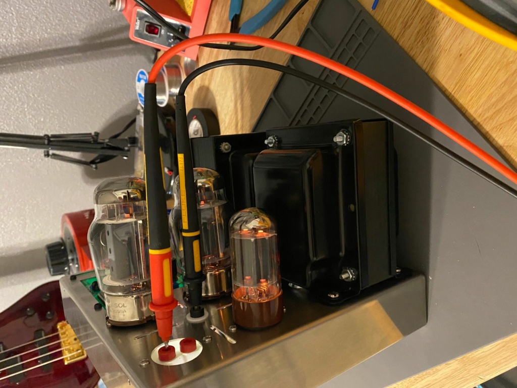
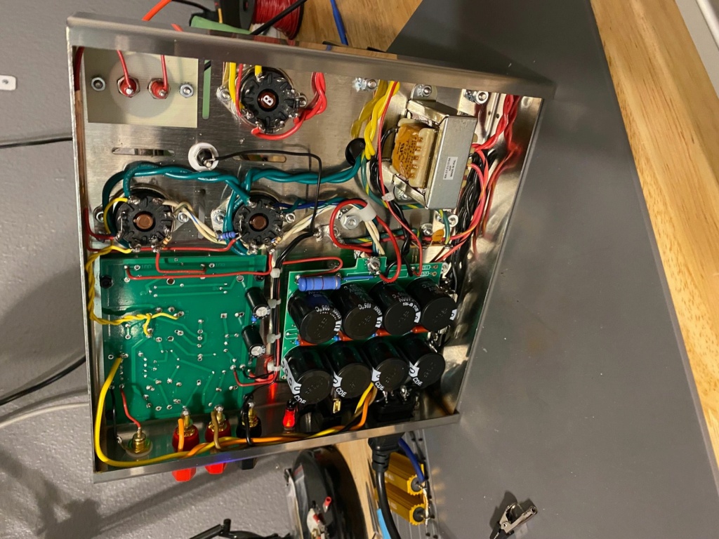
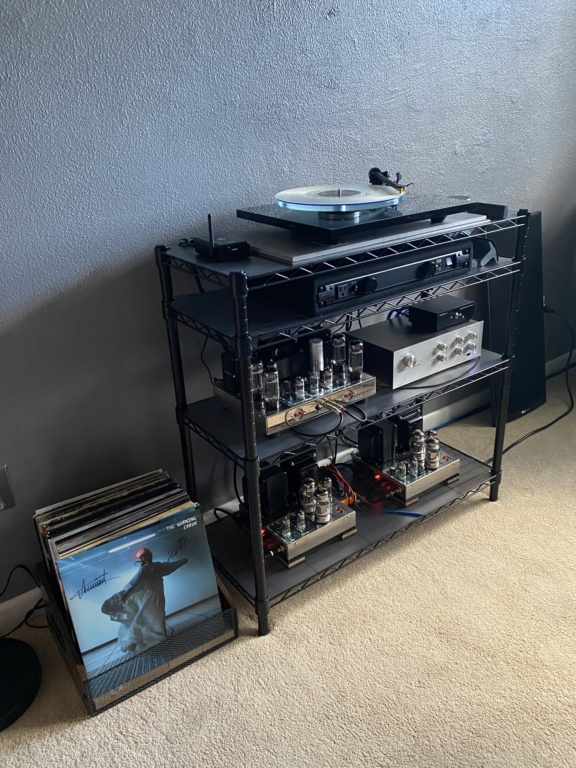
Last year I rescued a basket case original ST70. I chose the VTA driver kit as a more modern update. I loved it enough to embark on a MK3 clone build pieced together by several vendor's replacement items, but centered around the VTA drivers. Everything used for the MK3s was new except for original output iron. Scored a nice pair of OPTs that started me on this project.
The amps have been up and running for months and sound wonderful. There is one nagging question left unanswered. I asked on another forum of knowledgeable tube folks and have tried to reason it out myself. I don't feel it has been completely addressed.
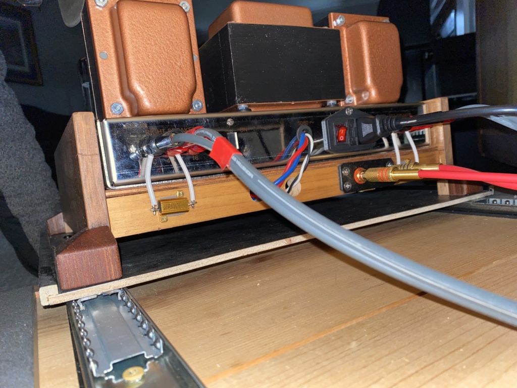
On most MK3 (re)builds and pretty much all original MK3s there is a 680 ohm resistor between the common and 16 ohm speaker tap. The assumption of many is this is a no-load protection for the transformers. I suppose it could be, as some custom builds that have the resistor installed have it between the common and 8 ohm tap, as the 16 ohm tap goes right to the NFB lug on the driver. It is drawn on the original MK3 schematics at the 16 ohm tap, and then the 16 goes to NFB.
My original thought was it was part of the NFB circuit and that by installing the VTA driver it may not be needed and longer. There is plausibility in the no load protection, except if that was the case, why doesn't the ST70 also have it?
In any case, I always wonder about stuff that can't be readily explained. I completed square wave tests at 20, 1K and 10K with and without the resistor and found no difference with it installed between common and 8 or 16 ohms. I decided to not install it in my amps.
Does anyone here actually know why that resistor is in the original schematic? I'd love to have this answered!
My MK 3 clones.


