


Hey guys!
I'm a newbie both in electronics assembly and here on the forum. I will need your help.
Initially I have some doubts about the cabinet. I would be grateful if someone could help.
1 - Could anyone tell me the height of the PCB after all the components have been soldered? Specifically, I would like to know the height of the components highlighted in the attached photo.
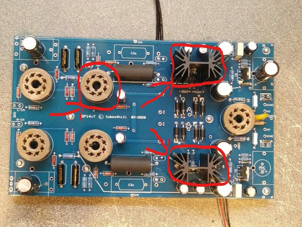
The question is necessary because I intend to mount the preamp with the tubes exposed. I will use 1 pair of LINLAI E-6SN7 and 1 pair of SHUGUANG TREASURE Z in them. I would like to make only 5 perforations in the upper part of the case. Leaving only the tubes exposed.
2 - Is aluminum a good material for assembly?
3 - Any special recommendations regarding painting the cabinet? I already know that the AC input and the grounding point must be in direct contact with the metal. Any other points? Any recommendations regarding paint?
4 - Does anyone know the minimum width and depth to accommodate the PCB and transformers at a safe distance? By the way, would mounting in a very large cabinet harm the performance of the equipment because longer wires are needed?
grateful!
I'm a newbie both in electronics assembly and here on the forum. I will need your help.
Initially I have some doubts about the cabinet. I would be grateful if someone could help.
1 - Could anyone tell me the height of the PCB after all the components have been soldered? Specifically, I would like to know the height of the components highlighted in the attached photo.
The question is necessary because I intend to mount the preamp with the tubes exposed. I will use 1 pair of LINLAI E-6SN7 and 1 pair of SHUGUANG TREASURE Z in them. I would like to make only 5 perforations in the upper part of the case. Leaving only the tubes exposed.
2 - Is aluminum a good material for assembly?
3 - Any special recommendations regarding painting the cabinet? I already know that the AC input and the grounding point must be in direct contact with the metal. Any other points? Any recommendations regarding paint?
4 - Does anyone know the minimum width and depth to accommodate the PCB and transformers at a safe distance? By the way, would mounting in a very large cabinet harm the performance of the equipment because longer wires are needed?
grateful!
