The Dynaco Tube Audio Forum

Would you like to react to this message? Create an account in a few clicks or log in to continue.
The Dynaco Tube Audio Forum

Dedicated to the restoration and preservation of all original Dynaco tube audio equipment - Customer support for Tubes4hifi VTA tube amp and preamp kits and all Dynakitparts.com products


5 posters

    Newbie problems with a ST-70 rebuild VTA70 driver board / bias display: no sound

    avatar
    fmzip


    Posts : 18
    Join date : 2023-03-10

    Newbie problems with a ST-70 rebuild VTA70 driver board / bias display: no sound Empty Newbie problems with a ST-70 rebuild VTA70 driver board / bias display: no sound

    Post by fmzip Fri Nov 03, 2023 8:09 am

    I purchased an ST-70 and decided to rebuild it. I don't know if the unit worked, or not prior to me touching it. As far as my skill set goes, I know how to use a multimeter, solder, read color codes assemble a circuit board, follow a wiring diagram. That's about it.

    This is what was done with the ST70 from its original state
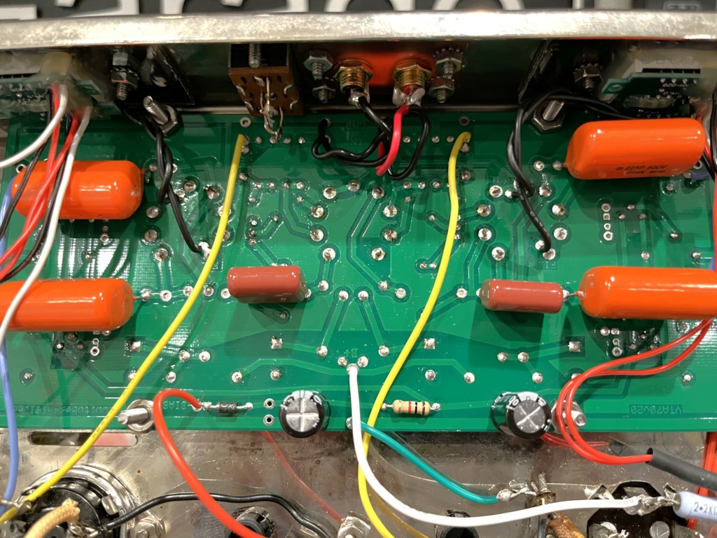
    Tubes4hifi VTA Driver Board installed
    Tubes4hifi bias display board kit installed
    Power Cap replaced
    4 ohm tap being used only

    All the tubes test good. The bias sets correctly to .40 per the assembly instructions. Voltage reading at B+ input of the VTA driver board measures 386VDC which is within range of the 380-400vdc in the instructions. I believe my preamp is working properly as I tested it with another amplifier. The preamp I build from scratch which is an Erhard audio Z5 line stage with linear power supply. Unfortunately, I no longer have a spare amp to test it with. Is there a simple way for me to confirm that a signal is coming out of it?

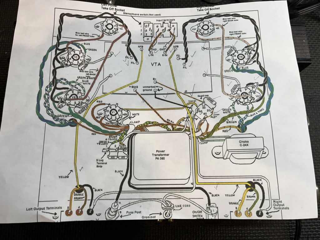
    What other areas should I check/measure on the ST70 and for what specific voltages? I read things like "check cathode voltage" check transfomer and choke voltages" but I do not know what a cathode is, I know what the transformer/choke is but how/where do I measure and for what? If someone said check pin "xyz" on output tube "xyz", voltage should be "xyz" VDC I could follow that. If Someone said connect positive side of meter to green/white wire and black probe to ground, reading should be "xyz" voltage I could do that as well. Long and short, I can follow specific instructions but I am not a technician, I can read a schematic to discern what parts are called out, but that would be the extent of it

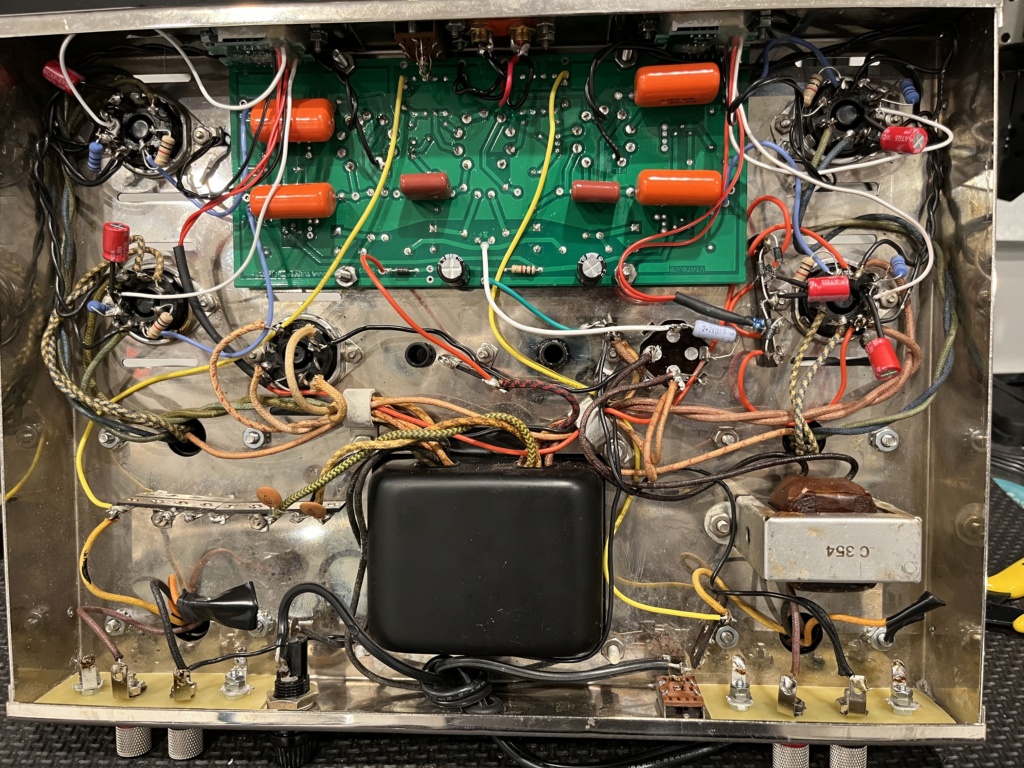
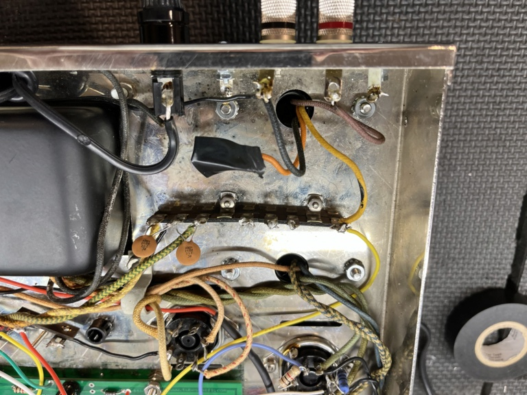
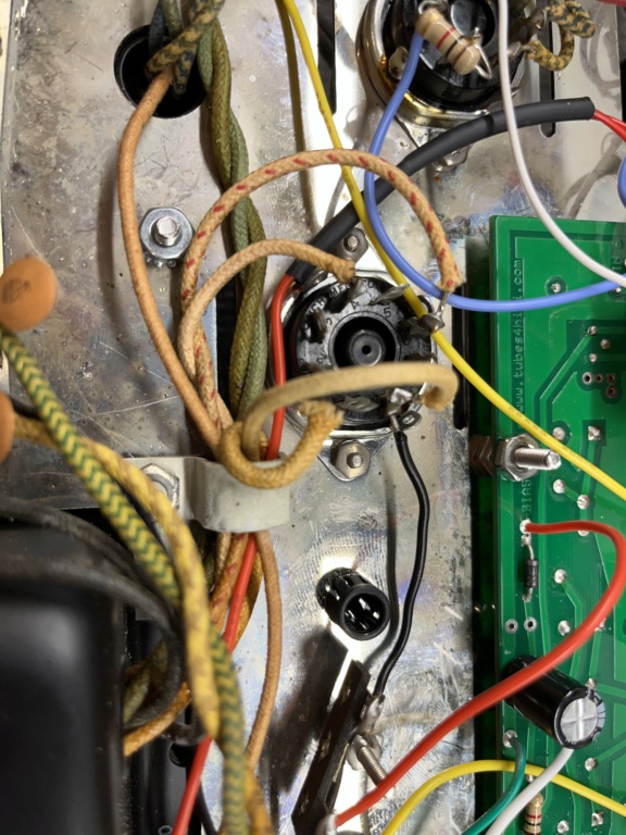
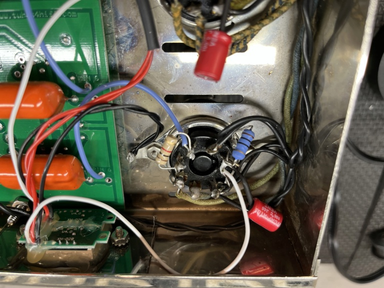
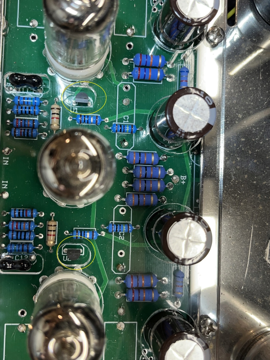
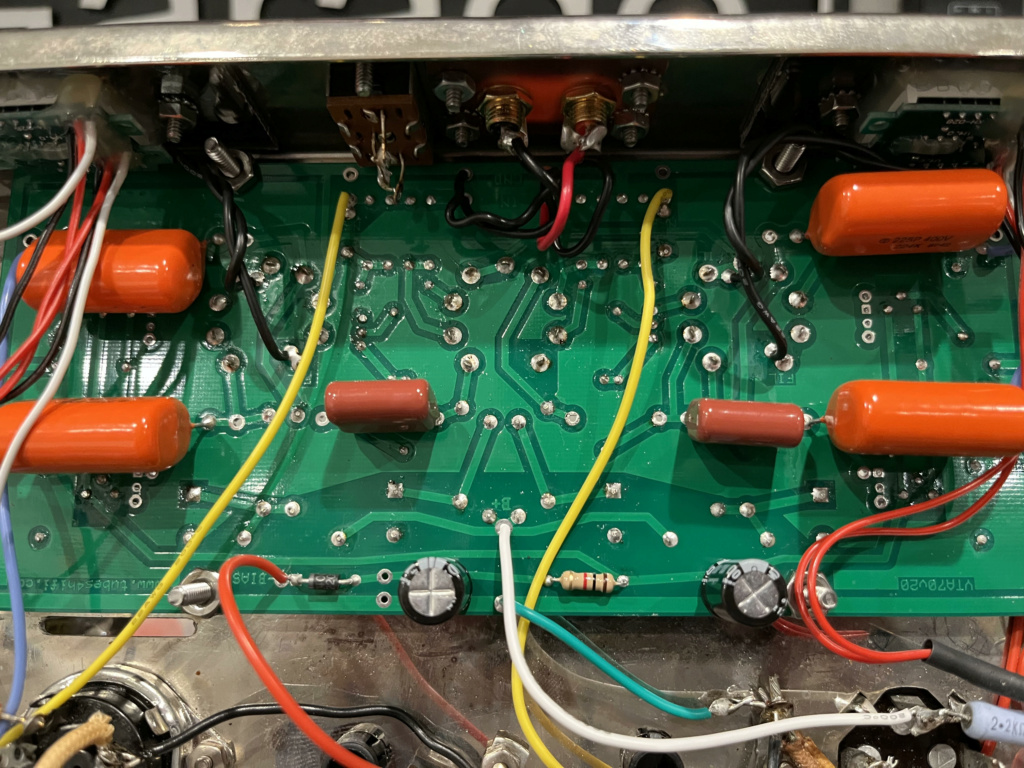
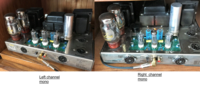
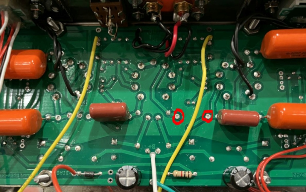
    Here are some photos of the build. Maybe someone can see something glaringly obvious? I rechecked all my wiring and solder joints many times over.
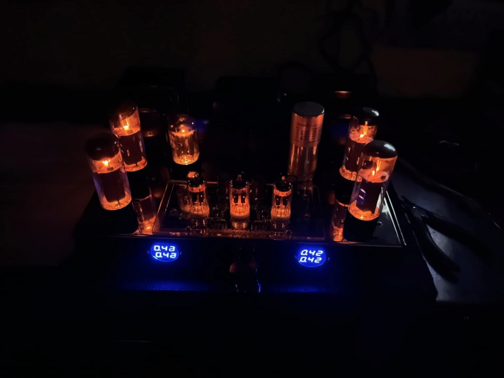
Newbie problems with a ST-70 rebuild VTA70 driver board / bias display: no sound 39868710
    avatar
    fmzip


    Posts : 18
    Join date : 2023-03-10

    Newbie problems with a ST-70 rebuild VTA70 driver board / bias display: no sound Empty Re: Newbie problems with a ST-70 rebuild VTA70 driver board / bias display: no sound

    Post by fmzip Fri Nov 03, 2023 8:10 am

    moreNewbie problems with a ST-70 rebuild VTA70 driver board / bias display: no sound Img_5313
    Newbie problems with a ST-70 rebuild VTA70 driver board / bias display: no sound Img_5312
    avatar
    fmzip


    Posts : 18
    Join date : 2023-03-10

    Newbie problems with a ST-70 rebuild VTA70 driver board / bias display: no sound Empty Re: Newbie problems with a ST-70 rebuild VTA70 driver board / bias display: no sound

    Post by fmzip Fri Nov 03, 2023 8:11 am

    Newbie problems with a ST-70 rebuild VTA70 driver board / bias display: no sound Img_5315
    Newbie problems with a ST-70 rebuild VTA70 driver board / bias display: no sound Img_5314
    Newbie problems with a ST-70 rebuild VTA70 driver board / bias display: no sound Img_5316
    avatar
    fmzip


    Posts : 18
    Join date : 2023-03-10

    Newbie problems with a ST-70 rebuild VTA70 driver board / bias display: no sound Empty Re: Newbie problems with a ST-70 rebuild VTA70 driver board / bias display: no sound

    Post by fmzip Fri Nov 03, 2023 8:12 am

    Newbie problems with a ST-70 rebuild VTA70 driver board / bias display: no sound Img_5317
    Newbie problems with a ST-70 rebuild VTA70 driver board / bias display: no sound Img_5319
    Newbie problems with a ST-70 rebuild VTA70 driver board / bias display: no sound Img_5318
    avatar
    fmzip


    Posts : 18
    Join date : 2023-03-10

    Newbie problems with a ST-70 rebuild VTA70 driver board / bias display: no sound Empty Re: Newbie problems with a ST-70 rebuild VTA70 driver board / bias display: no sound

    Post by fmzip Fri Nov 03, 2023 8:14 am

    moreNewbie problems with a ST-70 rebuild VTA70 driver board / bias display: no sound Img_5325
    Newbie problems with a ST-70 rebuild VTA70 driver board / bias display: no sound Img_5324
    Newbie problems with a ST-70 rebuild VTA70 driver board / bias display: no sound Img_5323
    avatar
    fmzip


    Posts : 18
    Join date : 2023-03-10

    Newbie problems with a ST-70 rebuild VTA70 driver board / bias display: no sound Empty Re: Newbie problems with a ST-70 rebuild VTA70 driver board / bias display: no sound

    Post by fmzip Fri Nov 03, 2023 8:15 am

    Newbie problems with a ST-70 rebuild VTA70 driver board / bias display: no sound Img_5326
    Bob Latino
    Bob Latino
    Admin


    Posts : 3263
    Join date : 2008-11-26
    Location : Massachusetts

    Newbie problems with a ST-70 rebuild VTA70 driver board / bias display: no sound Empty Re: Newbie problems with a ST-70 rebuild VTA70 driver board / bias display: no sound

    Post by Bob Latino Fri Nov 03, 2023 1:23 pm

    Do a full voltage check on the amp and see if any voltages are way out range ? Many times a voltage reading that deviates greatly from what it should be can give you a clue as to what is wrong with the amp ? See chart below ..
    Bob

    Voltage readings

        * Note # 1 – Make sure you have your meter set to AC or DC as mentioned below. Ground is any point on the chassis frame. Place the black or negative probe on the chassis and the red or positive probe on the point mentioned. All tubes should be plugged in, inputs shorted or connected to your preamp, speakers connected and no signal should be running through the amplifier. Be careful not to cross two pins with the positive probe !
        * Note # 2 – Readings very slightly above or very slightly below the range are not normally a sign of a problem. Line voltages vary slightly throughout the country. Differences in the 5AR4 rectifier tube can cause variations also. The use of a solid state rectifier in place of the 5AR4 may cause some voltages to be higher.

                      5AR4 –               Pin 2 to ground – 420 - 450 volts DC
                                                Pin 8 to ground – 420 - 450 volts DC
                                                Pin 4 to ground – 355 - 380 volts AC
                                                Pin 6 to ground – 355 - 380 volts AC
                Any EL34 – Pin 1 or pin 8 to ground – approx .400 volts DC (depends on bias setting)
                                 Across pins 2 and 7 – 6.0 – 6.8 volts AC
                                              Pin 3 to ground – 400 - 435 volts DC
                                              Pin 4 to ground – 400 - 435 volts DC (2 or 3 volts higher than pin 3)
                                              Pin 5 to ground – minus 30 to minus 40 volts DC
                                              Pin 6 to ground – minus 30 to minus 40 volts DC
                                              Pin 8 to ground – approx .400 volts DC (depends on bias setting)
                   Quad cap –-- Section # 1 (square symbol) –------ 420 – 450 volts DC
                                                        Section # 2 (half circle symbol) --- 420 – 445 volts DC
                                                        Section # 3 (NO symbol or a circle symbol) ------------- 420 – 445 volts DC
                                                        Section # 4 (triangle symbol) ------  380 – 420 volts DC
                            Central 12AU7 – Pin 1 or pin 6 to ground > 140 – 165 volts DC
                            Two outer 12AU7’s – Pin 1 or pin 6 to ground > 250 – 280 volts DC
                               Any 12AU7 – across the two incoming heater wires > 6.0 - 6.8 volts AC
                             “-50 VAC” on driver board > 48 – 55 volts AC
                     “B+” on driver board > 370 – 410 volts DC
    avatar
    fmzip


    Posts : 18
    Join date : 2023-03-10

    Newbie problems with a ST-70 rebuild VTA70 driver board / bias display: no sound Empty Re: Newbie problems with a ST-70 rebuild VTA70 driver board / bias display: no sound

    Post by fmzip Fri Nov 03, 2023 1:49 pm

    Thank you so much Bob, this is perfect I can follow this instructions

    Could I trouble you for clarifying the following  I noted in bold:

     Central 12AU7 – Pin 1 or pin 6 to ground > 140 – 165 volts DC  When looking from the bottom side of the VTA70 board I circled in red what I think is pin 1 on each tube, is this correct?
    Two outer 12AU7’s – Pin 1 or pin 6 to ground > 250 – 280 volts DC
    Any 12AU7 – across the two incoming heater wires > 6.0 - 6.8 volts AC I assume these wires I circled in yellow are the heater wires, is this correct? You mention any 12au7 but I only see these two wires attached to the two outer 12au7's
     “-50 VAC” on driver board > 48 – 55 volts AC I assume this marked on the board somewhere? I am not home at the moment. Where am I putting my two probes to measure this voltage? Does the red probe go to the -50VAC point on the PCB and the black to ground?
    Across pins 2 and 7 – 6.0 – 6.8 volts AC Your directions state to have the black probe to ground. How would I measure "across" these two points if the black probe is grounded?

    Newbie problems with a ST-70 rebuild VTA70 driver board / bias display: no sound Img_5327
    Newbie problems with a ST-70 rebuild VTA70 driver board / bias display: no sound Img_5328


    Bob Latino wrote:Do a full voltage check on the amp and see if any voltages are way out range ? Many times a voltage reading that deviates greatly from what it should be can give you a clue as to what is wrong with the amp ? See chart below ..
    Bob

    Voltage readings

        * Note # 1 – Make sure you have your meter set to AC or DC as mentioned below. Ground is any point on the chassis frame. Place the black or negative probe on the chassis and the red or positive probe on the point mentioned. All tubes should be plugged in, inputs shorted or connected to your preamp, speakers connected and no signal should be running through the amplifier. Be careful not to cross two pins with the positive probe !
        * Note # 2 – Readings very slightly above or very slightly below the range are not normally a sign of a problem. Line voltages vary slightly throughout the country. Differences in the 5AR4 rectifier tube can cause variations also. The use of a solid state rectifier in place of the 5AR4 may cause some voltages to be higher.

                      5AR4 –               Pin 2 to ground – 420 - 450 volts DC
                                                Pin 8 to ground – 420 - 450 volts DC
                                                Pin 4 to ground – 355 - 380 volts AC
                                                Pin 6 to ground – 355 - 380 volts AC
                Any EL34 – Pin 1 or pin 8 to ground – approx .400 volts DC (depends on bias setting)
                                 Across pins 2 and 7 – 6.0 – 6.8 volts AC
                                              Pin 3 to ground – 400 - 435 volts DC
                                              Pin 4 to ground – 400 - 435 volts DC (2 or 3 volts higher than pin 3)
                                              Pin 5 to ground – minus 30 to minus 40 volts DC
                                              Pin 6 to ground – minus 30 to minus 40 volts DC
                                              Pin 8 to ground – approx .400 volts DC (depends on bias setting)
                   Quad cap –-- Section # 1 (square symbol) –------ 420 – 450 volts DC
                                                        Section # 2 (half circle symbol) --- 420 – 445 volts DC
                                                        Section # 3 (NO symbol or a circle symbol) ------------- 420 – 445 volts DC
                                                        Section # 4 (triangle symbol) ------  380 – 420 volts DC
                            Central 12AU7 – Pin 1 or pin 6 to ground > 140 – 165 volts DC
                            Two outer 12AU7’s – Pin 1 or pin 6 to ground > 250 – 280 volts DC
                               Any 12AU7 – across the two incoming heater wires > 6.0 - 6.8 volts AC
                             “-50 VAC” on driver board > 48 – 55 volts AC
                     “B+” on driver board > 370 – 410 volts DC
    avatar
    fmzip


    Posts : 18
    Join date : 2023-03-10

    Newbie problems with a ST-70 rebuild VTA70 driver board / bias display: no sound Empty Re: Newbie problems with a ST-70 rebuild VTA70 driver board / bias display: no sound

    Post by fmzip Sat Nov 04, 2023 12:35 pm

    Hi Bob, here are my measurements and few questions noted in bold. I just connected a different source and I do have audio out of only one channel:

    5AR4 –              
    Pin 2 to ground – 420 - 450 volts DC =460
    Pin 8 to ground – 420 - 450 volts DC =460
    Pin 4 to ground – 355 - 380 volts AC= 369
    Pin 6 to ground – 355 - 380 volts AC= 369
    Any EL34 –
    Pin 1 or pin 8 to ground – approx .400 volts DC (depends on bias setting) =.40
    Across pins 2 and 7 – 6.0 – 6.8 volts AC = I don’t understand how to measure this. The directions provided state to have the black probe to ground. Am I supposed to take the black probe and put it on pin 2 and the red probe on pin7? Or am I taking the red probe to pin 2 and ground and measure, then the same with pin 7 and ground and measure. The word “across” to me means the take the measurements across these two pins, black probe on one, read probe on the other. If so, which probe on what or does it matter?
    Pin 3 to ground – 400 - 435 volts DC= 438
    Pin 4 to ground – 400 - 435 volts DC (2 or 3 volts higher than pin 3)= 441
    Pin 5 to ground – minus 30 to minus 40 volts DC= -36
    Pin 6 to ground – minus 30 to minus 40 volts DC= -36
    Pin 8 to ground – approx .400 volts DC (depends on bias setting) =.40
    Quad cap –-- Section # 1 (square symbol) –------ 420 – 450 volts DC=384
    Section # 2 (half circle symbol) --- 420 – 445 volts DC= 455
    Section # 3 (NO symbol or a circle symbol) ------------- 420 – 445 volts DC= 439
    Section # 4 (triangle symbol) ------  380 – 420 volts DC= 439
    Central 12AU7 – Pin 1 or pin 6 to ground > 140 – 165 volts DC= which is pin 1 looking at the bottom of the VTA70 Board?
    Two outer 12AU7’s – Pin 1 or pin 6 to ground > 250 – 280 volts DC= which is pin 1 looking at the bottom of the VTA70 Board?
    Any 12AU7 – across the two incoming heater wires > 6.0 - 6.8 volts AC= what/where are the heater wires. Again, if I think “across”, am I measuring across and the black probe is not connected to ground?
    “-50 VAC” on driver board > 48 – 55 volts AC =Where is this location on the VTA70 board?
    Bob Latino
    Bob Latino
    Admin


    Posts : 3263
    Join date : 2008-11-26
    Location : Massachusetts

    Newbie problems with a ST-70 rebuild VTA70 driver board / bias display: no sound Empty Re: Newbie problems with a ST-70 rebuild VTA70 driver board / bias display: no sound

    Post by Bob Latino Sun Nov 05, 2023 8:43 am

    RE: > “-50 VAC” on driver board > 48 – 55 volts AC =Where is this location on the VTA70 board?" This point is where the red/black wire from the power transformer connects to the driver board. If you have bias voltage then you will have the proper voltage at this point."

    Since you have sound on one channel try these 3 items in this order ..

    1. First make sure that your audio source is working on the missing channel.

    2. Check the interconnect and speaker connections on the missing channel.

    3. With the amp upside down with the bottom cover off and the amp playing music at a low level, use an insulated object like a plastic pen to tap lightly on all the solder connections on the missing channel. If the sound comes back on even for a split second, you may have found a bad solder connection. Turn the amp OFF and resolder that connection.

    Bob
    avatar
    fmzip


    Posts : 18
    Join date : 2023-03-10

    Newbie problems with a ST-70 rebuild VTA70 driver board / bias display: no sound Empty Re: Newbie problems with a ST-70 rebuild VTA70 driver board / bias display: no sound

    Post by fmzip Sun Nov 05, 2023 9:57 pm

    Bob Latino wrote:RE: > “-50 VAC” on driver board > 48 – 55 volts AC =Where is this location on the VTA70 board?" This point is where the red/black wire from the power transformer connects to the driver board. If you have bias voltage then you will have the proper voltage at this point."

    Since you have sound on one channel try these 3 items in this order ..

    1. First make sure that your audio source is working on the missing channel.

    2. Check the interconnect and speaker connections on the missing channel.

    3. With the amp upside down with the bottom cover off and the amp playing music at a low level, use an insulated object like a plastic pen to tap lightly on all the solder connections on the missing channel. If the sound comes back on even for a split second, you may have found a bad solder connection. Turn the amp OFF and resolder that connection.

    Bob

    Thanks for the suggestions Bob. Swapping left and right on the source output, no difference sound only on one side. Swapped speakers and wires, still only sound on one side. Tapped all the solder joints, nothing different. Hate to give up but I'm not sure what else to look for. I'd hate to retouch solder joints on the PCB that don't look questionable. Can you tell me which reference designators are specific to the right channel?
    Bob Latino
    Bob Latino
    Admin


    Posts : 3263
    Join date : 2008-11-26
    Location : Massachusetts

    Newbie problems with a ST-70 rebuild VTA70 driver board / bias display: no sound Empty Re: Newbie problems with a ST-70 rebuild VTA70 driver board / bias display: no sound

    Post by Bob Latino Mon Nov 06, 2023 9:55 am

    There is also the possibility that the output transformer for that channel is bad ? Make sure that the amp is OFF when you test all the resistances below.

    1. To test the secondary (speaker side) of the output transformer check to see if there is continuity between the negative terminal and the 4, 8 and 16 ohm terminals. You should get a very low resistance on all three terminals - probably less than 2 ohms.

    2. To test the primary side check that you have continuity and some resistance between the BLUE and the BLUE/WHITE wire and the GREEN and the GREEN/WHITE wire on that channel.

    3. Also on the primary side test the RED wire for that output transformer that is now connected to the quad cap to the other primary wires > the BLUE, the BLUE/WHITE, the GREEN and the GREEN/WHITE. See if you get some resistance from the RED to those other four wires.

    Bob
    avatar
    fmzip


    Posts : 18
    Join date : 2023-03-10

    Newbie problems with a ST-70 rebuild VTA70 driver board / bias display: no sound Empty Re: Newbie problems with a ST-70 rebuild VTA70 driver board / bias display: no sound

    Post by fmzip Mon Nov 06, 2023 2:45 pm

    Thanks Bob, all of these pass test as well....still no sound out of the right side


    Bob Latino wrote:There is also the possibility that the output transformer for that channel is bad ? Make sure that the amp is OFF when you test all the resistances below.

    1. To test the secondary (speaker side) of the output transformer check to see if there is continuity between the negative terminal and the 4, 8 and 16 ohm terminals. You should get a very low resistance on all three terminals - probably less than 2 ohms.

    2. To test the primary side check that you have continuity and some resistance between the BLUE and the BLUE/WHITE wire and the GREEN and the GREEN/WHITE wire on that channel.

    3. Also on the primary side test the RED wire for that output transformer that is now connected to the quad cap to the other primary wires > the BLUE, the BLUE/WHITE, the GREEN and the GREEN/WHITE. See if you get some resistance from the RED to those other four wires.

    Bob
    Bob Latino
    Bob Latino
    Admin


    Posts : 3263
    Join date : 2008-11-26
    Location : Massachusetts

    Newbie problems with a ST-70 rebuild VTA70 driver board / bias display: no sound Empty Re: Newbie problems with a ST-70 rebuild VTA70 driver board / bias display: no sound

    Post by Bob Latino Mon Nov 06, 2023 3:14 pm

    At this point you should probably consider taking the amp to a place in your area that works on tube guitar amps. They should be able to check out your amp and give you an answer as to why that one channel does not work ?

    Bob

    avatar
    fmzip


    Posts : 18
    Join date : 2023-03-10

    Newbie problems with a ST-70 rebuild VTA70 driver board / bias display: no sound Empty Re: Newbie problems with a ST-70 rebuild VTA70 driver board / bias display: no sound

    Post by fmzip Mon Nov 06, 2023 3:56 pm

    Bob Latino wrote:At this point you should probably consider taking the amp to a place in your area that works on tube guitar amps. They should be able to check out your amp and give you an answer as to why that one channel does not work ?

    Bob


    I agree Bob. Found two places that have vast experience with this amp.....

    Hate to give up but I think it's time. Thanks for your help, will post what they ultimately find
    avatar
    New2Tubez


    Posts : 184
    Join date : 2018-03-20
    Location : NY

    Newbie problems with a ST-70 rebuild VTA70 driver board / bias display: no sound Empty Re: Newbie problems with a ST-70 rebuild VTA70 driver board / bias display: no sound

    Post by New2Tubez Tue Nov 07, 2023 9:42 am

    Hopefully not a side track as I don’t know enough but does your board have the LM336’s? I had one of these go bad on my ST120. I heard a rustling sound and suddenly one channel had greatly reduced volume. Obviously Bob is the authority here but it was just a thought…
    avatar
    fmzip


    Posts : 18
    Join date : 2023-03-10

    Newbie problems with a ST-70 rebuild VTA70 driver board / bias display: no sound Empty Re: Newbie problems with a ST-70 rebuild VTA70 driver board / bias display: no sound

    Post by fmzip Tue Nov 07, 2023 9:55 am

    New2Tubez wrote:Hopefully not a side track as I don’t know enough but does your board have the LM336’s? I had one of these go bad on my ST120. I heard a rustling sound and suddenly one channel had greatly reduced volume. Obviously Bob is the authority here  but it was just a thought…

    LM334's on mine but thanks for pointing this out!

    Looks like I have a part in backwards....will check when I get homeNewbie problems with a ST-70 rebuild VTA70 driver board / bias display: no sound Img_5329
    Bob Latino
    Bob Latino
    Admin


    Posts : 3263
    Join date : 2008-11-26
    Location : Massachusetts

    Newbie problems with a ST-70 rebuild VTA70 driver board / bias display: no sound Empty Re: Newbie problems with a ST-70 rebuild VTA70 driver board / bias display: no sound

    Post by Bob Latino Tue Nov 07, 2023 10:14 am

    fmzip wrote:
    New2Tubez wrote:Hopefully not a side track as I don’t know enough but does your board have the LM336’s? I had one of these go bad on my ST120. I heard a rustling sound and suddenly one channel had greatly reduced volume. Obviously Bob is the authority here  but it was just a thought…

    LM334's on mine I believe

    Yes - The small LM334 (if it goes out) will cause a major drop in volume on that channel. The sound level will be very low but the channel will still give some output. Note 1 > the most common cause of an LM334 going bad is that one of the two side 12AU7 goes bad and takes the LM334 with it OR someone puts a 12AT7 or a 12AX7 in place of one of the two side 12AU7's. Note 2 > Up until about April of 2012 the VTA ST-70 driver board did use 12AT7's but all VTA amps now use 12AU7 type tubes. You can also use the military/industrial versions of a 12AU7 > 5963, 5814 and 6189 tubes.

    Note 3 > Tubes4hifi now also sells an octal version of the board with 6SN7 tubes. A 6SN7 is just an octal version of a 12AU7.

    Bob
    avatar
    fmzip


    Posts : 18
    Join date : 2023-03-10

    Newbie problems with a ST-70 rebuild VTA70 driver board / bias display: no sound Empty Re: Newbie problems with a ST-70 rebuild VTA70 driver board / bias display: no sound

    Post by fmzip Tue Nov 07, 2023 10:57 pm

    Unfortunately, reversing the part didn't resolve it. Replacing the part didn't either.

    Giving it a tech tomorrow, will post back what was found
    avatar
    New2Tubez


    Posts : 184
    Join date : 2018-03-20
    Location : NY

    Newbie problems with a ST-70 rebuild VTA70 driver board / bias display: no sound Empty Re: Newbie problems with a ST-70 rebuild VTA70 driver board / bias display: no sound

    Post by New2Tubez Wed Nov 08, 2023 12:43 am

    "New2Tubez wrote:
    Hopefully not a side track as I don’t know enough but does your board have the LM336’s? I had one of these go bad on my ST120. I heard a rustling sound and suddenly one channel had greatly reduced volume. Obviously Bob is the authority here  but it was just a thought…

    LM334's on mine but thanks for pointing this out!"

    Meant to say LM334. I tried to look it up but limited success on my phone while also trying to post.
    Sorry this wasn't the cure for yours.
    avatar
    fmzip


    Posts : 18
    Join date : 2023-03-10

    Newbie problems with a ST-70 rebuild VTA70 driver board / bias display: no sound Empty Re: Newbie problems with a ST-70 rebuild VTA70 driver board / bias display: no sound

    Post by fmzip Wed Nov 08, 2023 11:14 am

    Hi Bob, have my tech looking at this now. The schematic I received with my order does not show all the parts on it. My tech was asking if there is a complete schematic available.

    He's making progress, no signal after the highlighted area. Wasn't sure if it is okay to post the schematic I have so here's a snip


    Newbie problems with a ST-70 rebuild VTA70 driver board / bias display: no sound 37144810
    avatar
    fmzip


    Posts : 18
    Join date : 2023-03-10

    Newbie problems with a ST-70 rebuild VTA70 driver board / bias display: no sound Empty Re: Newbie problems with a ST-70 rebuild VTA70 driver board / bias display: no sound

    Post by fmzip Wed Nov 08, 2023 2:06 pm

    Funny how when someone points out the mistake it becomes glaringly obvious!

    Can anyone see it......

    Another question, my bias on one tube is low at .34 and I ran out of range on the pot. The instructions say to replace two resistors with a 15K if more bias is needed. Would it be a 1/4W, 1/2W, 1% or 5% resistor to be used in it's place?

    Newbie problems with a ST-70 rebuild VTA70 driver board / bias display: no sound Unname10
    Bob Latino
    Bob Latino
    Admin


    Posts : 3263
    Join date : 2008-11-26
    Location : Massachusetts

    Newbie problems with a ST-70 rebuild VTA70 driver board / bias display: no sound Empty Re: Newbie problems with a ST-70 rebuild VTA70 driver board / bias display: no sound

    Post by Bob Latino Wed Nov 08, 2023 4:49 pm

    It is hard to tell but is that .10 uF interstage (orange drop) cap on the bottom of the driver board (on the right side of the photo) set into the wrong two board eyelets ?

    Bob

    knotscott likes this post

    knotscott
    knotscott


    Posts : 58
    Join date : 2019-12-28
    Location : Rochester, NY

    Newbie problems with a ST-70 rebuild VTA70 driver board / bias display: no sound Empty Re: Newbie problems with a ST-70 rebuild VTA70 driver board / bias display: no sound

    Post by knotscott Fri Nov 10, 2023 1:41 pm

    Bob Latino wrote:It is hard to tell but is that .10 uF interstage (orange drop) cap on the bottom of the driver board (on the right side of the photo) set into the wrong two board eyelets ?

    Bob


    Not surprisingly, I think Bob's correct.  I checked pics of mine, and even though on mine the same caps are on the opposite side of the board, it does look like the leads go to different holes.  

    Newbie problems with a ST-70 rebuild VTA70 driver board / bias display: no sound Vta9u10
    Newbie problems with a ST-70 rebuild VTA70 driver board / bias display: no sound Vta70i10
    avatar
    New2Tubez


    Posts : 184
    Join date : 2018-03-20
    Location : NY

    Newbie problems with a ST-70 rebuild VTA70 driver board / bias display: no sound Empty Re: Newbie problems with a ST-70 rebuild VTA70 driver board / bias display: no sound

    Post by New2Tubez Fri Nov 10, 2023 2:31 pm

    Here’s mine:
    rl=https://servimg.com/view/19911748/68]Newbie problems with a ST-70 rebuild VTA70 driver board / bias display: no sound 12f9a810[/url]

    knotscott and itrfguy like this post


    Sponsored content


    Newbie problems with a ST-70 rebuild VTA70 driver board / bias display: no sound Empty Re: Newbie problems with a ST-70 rebuild VTA70 driver board / bias display: no sound

    Post by Sponsored content


      Current date/time is Sun Apr 28, 2024 11:37 am