+2
stewdan
WildOne
6 posters
Am I missing something here???

WildOne- Posts : 6
Join date : 2011-05-03
Location : Great Northwest
- Post n°1
 Am I missing something here???

stewdan- Posts : 234
Join date : 2010-03-07
Age : 86
Location : Houston Texas
- Post n°2
 ST70 Differences
Hi --
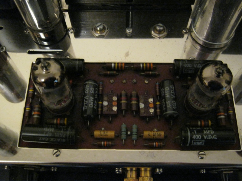
I am no expert, but the working amp which to me looks stock uses a tube rectifier (the GZ34/5AR4 tube located to the left of the Tall Silver Quad Capacitor).
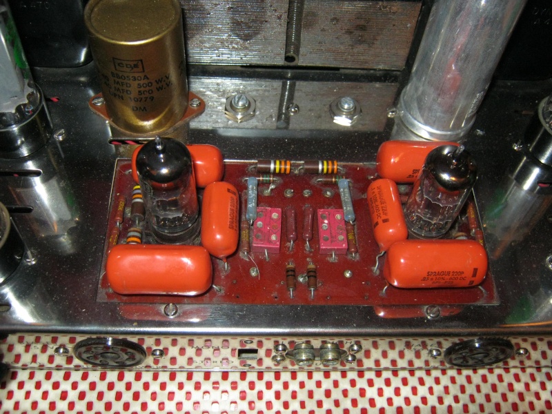
The non-working ST70 with the orange drop caps has what looks like a two-section capacitor (bronze color) sitting where a stock ST70 has its GZ34 recitifer tube. So, I would assume that this unit is using solid state rectification (somewhere on the bottom of the chassis). That plus the extra cap stages in the bronze color cap caused some circuit changes to be made on the circuit board that contains the orange drops. If you take the bottom cover off and post some pictures of the underside of this amp, we may be able to tell exactly whats happening.
Hope that helps, Stew

WildOne- Posts : 6
Join date : 2011-05-03
Location : Great Northwest
- Post n°3
 Re: Am I missing something here???

WildOne- Posts : 6
Join date : 2011-05-03
Location : Great Northwest
- Post n°4
 Re: Am I missing something here???
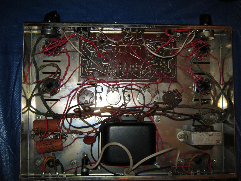
Man what a mess! What have they done to my beloved amp? I think she needs to be taken to the DR. I needed a project and I think this is a good one to start with. But I must admit that this is all new to me and I have bought my equipment and been reading up a storm. I absorb very well so if I can have a mentor to help me through it I will be fine. Maybe someone can take the pic and put it into paint and direct me with diagrams on the pic to fallow?
Anyway here she is and not to much to look at.
WO
Here is a pic of just the amps I have collected in the last 35-40 days. These are local finds, I have a couple more coming by mail
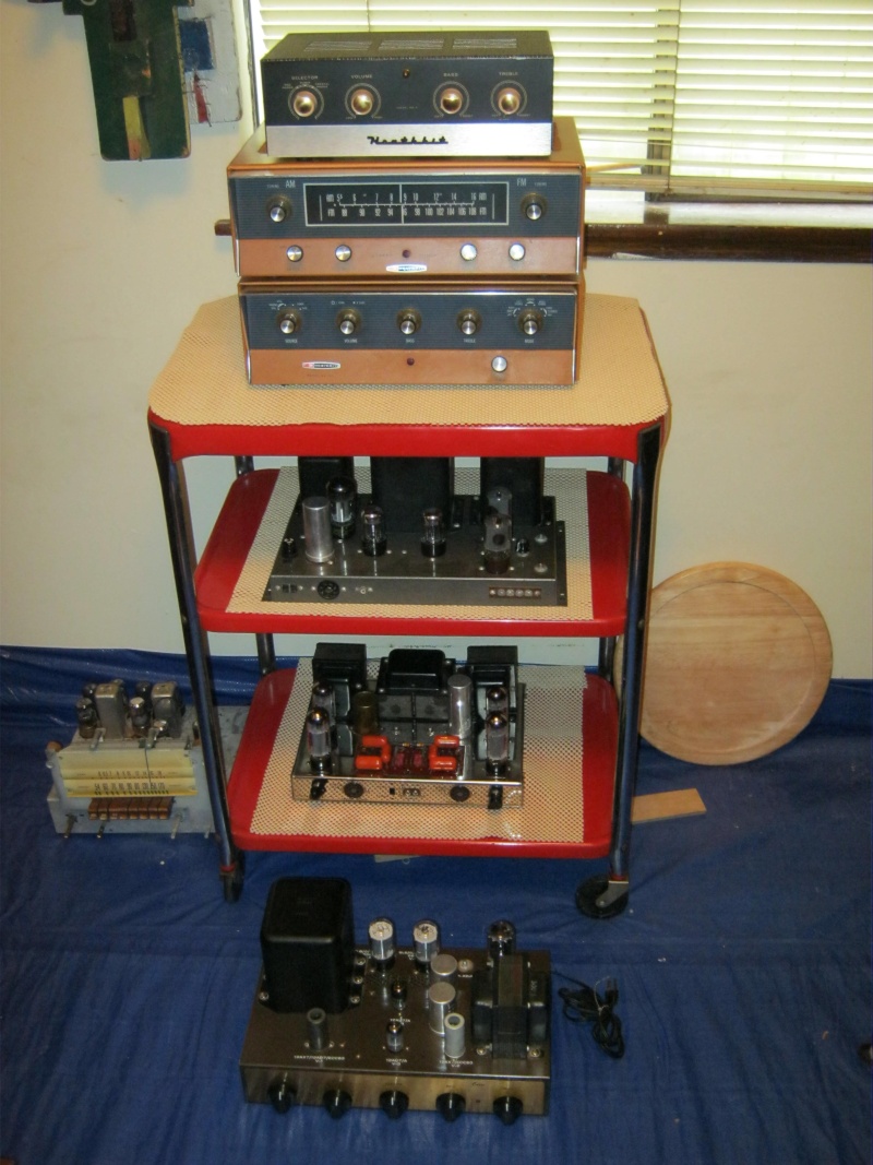
Anyway here she is and not to much to look at.
WO
Here is a pic of just the amps I have collected in the last 35-40 days. These are local finds, I have a couple more coming by mail

Last edited by WildOne on Wed May 04, 2011 10:46 am; edited 1 time in total

WildOne- Posts : 6
Join date : 2011-05-03
Location : Great Northwest
- Post n°5
 Re: Am I missing something here???

anbitet66- Posts : 143
Join date : 2009-12-23
Location : Valley Stream, NY
- Post n°6
 Re: Am I missing something here???
What is the troublesome amp [not]doing? The missing resistor and cap are for a filter network between the pentode/triode stages of each 7199. Not essential, but shouldn't be causing a lack of audio either.
BTW, I'd ask where the local sales are that you've frequented, but I'd probably be tempted to spend money I don't have .
.
Tony
BTW, I'd ask where the local sales are that you've frequented, but I'd probably be tempted to spend money I don't have
Tony

WildOne- Posts : 6
Join date : 2011-05-03
Location : Great Northwest
- Post n°7
 Re: Am I missing something here???
I seem to do well in finding stuff 
As for the problem?
Well I bought these from a guy who sells on ebay, He liked me and let me take both the st-70s for $450.
When he went to power this one up, he had a nice varaic with meters. He said as soon as he started to turn the dial that this one had a problem as it made the Amp meter jump up a few bars. He then shut it down and then hooked up the other one, This one did not make the meter jump and he went from 30v ac to 60 then 90 and full. About 10 min between.
So all I know is that it made the meter jump and he said it was a none working amp.
WO

stewdan- Posts : 234
Join date : 2010-03-07
Age : 86
Location : Houston Texas
- Post n°8
 Differences
Hi WO --
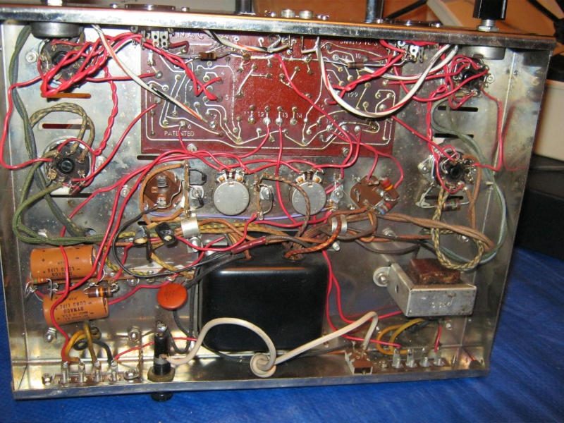
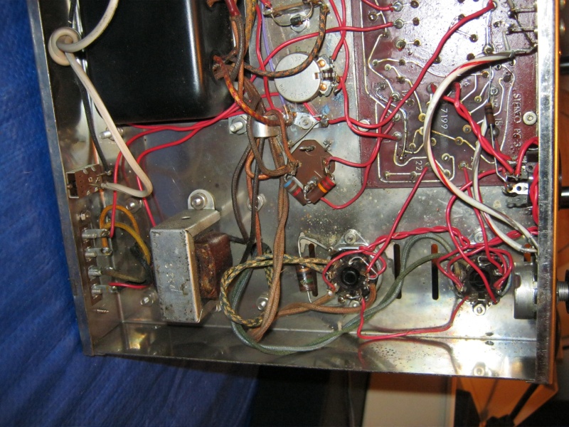
I looked at your underside pictures of the Orange Drop ST70 and this is what I found:
(1) the GZ34 was replaced with a couple of diodes.
(2) It also looks like one section of the Bronze colored two-stage capacitor is being used to replace the section of the Aluminum Quad Cap that would normally be driven by pin 8 of the GZ34 Rectifier tube.
(3)The Selenium Rectifier which would normally be located between the two tunable bias pots was also replaced by a diode, but this would not cause any circuit changes to the circuit board.
I compared your underside pictures with the pictorial layouts in the Dynaco Manual located at http://www.dynakitparts.com/store/manuals/Dyna-ST70.pdf which is a real clean manual, very sharp clear pictures. Your underside wiring to the circuit board looks consistant with the dynaco layouts except for the (1), (2) and (3) items.
Why the topside of the orange drop circuit board looks different than the working ST70 I can't tell, but may be due to the changes made by (1) and/or (2) above and were based on what the modifier wanted to do.
Maybe Bob or one of the other readers can cast some light on these mods.
Stew

Roy Mottram- Admin
- Posts : 1838
Join date : 2008-11-30
- Post n°9
 Re: Am I missing something here???
I can tell you from LOTS of experience that this is an easy fix, or a nightmare.
The nightmare is trying to spend WAY too many hours fixing up a stock ST70, lots of time and money,
and wind up with so-so (can I say mediocre?) sound quality.
The EASY fix, just a few hours, and guaranteed mind-blowing sound quality, is to replace all that old stock crap and unknown mods,
and simple put in a VTA70 driver board, along with putting the rectifier tube back in where that extra cap wound up.
PS - also keep the HK gear, and it's likely full of Telefunken 12AX7s. Replace the old caps.
Tube Nube- Posts : 707
Join date : 2008-12-06
Age : 61
Location : Calgary, AB
- Post n°10
 Re: Am I missing something here???
You wont hear much argument with that! The trusty old st 70 is a a truly modern classic with the modern driver board offered in the VTA. The performance is stunning, the cost modest.

sailor- Posts : 269
Join date : 2011-04-04
- Post n°11
 Re: Am I missing something here???
If I am looking at it correctly. You have a problem with the diodes. The 2 wires from the transformer are at each end of the solder strip. The 2 diode anodes should be connected one to each transformer wire. The 2 cathodes should be connected together and then to the capacitor. One diode is in backwards.

WildOne- Posts : 6
Join date : 2011-05-03
Location : Great Northwest
- Post n°12
 Re: Am I missing something here???
Can I ask you to take that pic and put it into paint and draw a arrow where you are talking about?
Thanks
WO
Thanks
WO

sailor- Posts : 269
Join date : 2011-04-04
- Post n°13
 Re: Am I missing something here???
Sorry, when it comes to graphics on the internet I am at a loss.
There are 3 diodes on the bottom of your problem amp. The one by it's self is for the bios. The 2 that are together are the replacement for the 5ar4. Go to your post 3 and look at the first picture or look at the bottom of your amp. There are 2 diodes on a solder strip next to a can cap. The 2 stripes on the diodes should be pointing or next to each other. The way they are wired one is producing + voltage the other - which I think cancels each other out. The one nearest the circuit board needs to be reversed. You should unsolder the cap from the diodes before making the change just in case you reverse the wrong diode. After reversing the diode and after removing the wire to the cap and all the tubes removed then fire it up and check the voltage where the diodes meet. It should be a positive voltage 400 to 550 volts. I get 550 volts on my diodes. Volt meter pos. probe on the diode connection neg. on chassis. If this does not get you any voltage you may have blown diodes or transformer.
There are 3 diodes on the bottom of your problem amp. The one by it's self is for the bios. The 2 that are together are the replacement for the 5ar4. Go to your post 3 and look at the first picture or look at the bottom of your amp. There are 2 diodes on a solder strip next to a can cap. The 2 stripes on the diodes should be pointing or next to each other. The way they are wired one is producing + voltage the other - which I think cancels each other out. The one nearest the circuit board needs to be reversed. You should unsolder the cap from the diodes before making the change just in case you reverse the wrong diode. After reversing the diode and after removing the wire to the cap and all the tubes removed then fire it up and check the voltage where the diodes meet. It should be a positive voltage 400 to 550 volts. I get 550 volts on my diodes. Volt meter pos. probe on the diode connection neg. on chassis. If this does not get you any voltage you may have blown diodes or transformer.

Roy Mottram- Admin
- Posts : 1838
Join date : 2008-11-30
- Post n°14
 Re: Am I missing something here???
WildOne,
the way to fix it is to put it back as original, like the other amp.
Take the two diodes out and put a rectifier tube back in. Much less likely to blow anything up.
Putting 500+v INSTANTLY on tubes is a bad idea. They need 15-20 seconds to warm up.
But to answer your question (if you HAVE to do it with diodes) here is a picture of how your amp should be,
and then another drawing of how it REALLY should be if you want to use diodes. Even 1000v diodes are gonna eventually weaken and blow up.
You need two pairs in series, with sharing resistors, but that will still blow the quad cap (it's only good for 500v) so you want to add two more capacitors also in series with sharing resistors.
But you can't beat doing it as was original.


Roy Mottram- Admin
- Posts : 1838
Join date : 2008-11-30
- Post n°15
 Re: Am I missing something here???
go back to my post 9, for the best way to fix it, but I wanted to give you the info you requested in your last post

sailor- Posts : 269
Join date : 2011-04-04
- Post n°16
 Re: Am I missing something here???
I agree with tubes4hifi. This is the wiring problem I spotted. And he is right about the cap. I am using caps wired for 760 volts.

