

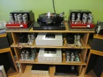
does anyone out there have some good pictures of the vta board installed in a mark III? thank you
3 posters
mar III vta pictures
wedg714- Posts : 74
Join date : 2011-11-23

stewdan- Posts : 231
Join date : 2010-03-07
Age : 85
Location : Houston Texas
Hi -- I am currently working on rebuilding two Mark 3's and this is what I did:
Go to Forum -- HOME, then Select "Dynaco Pictures" and you will find several Mark3-VTA installs with picture groups showing the underside of the VTA board with the wires attached. There are also "Picture Tutorials on the Web of the Mark3-VTA Board Install -- you can google these. If you can, print out some of the pictures!!!!!!!
A starting point (This was A MUST for me) is Bob Latino's Colorized Pictorial of the Original Mark III wires ===>> FORUM, look for a "Sticky: Free Dynaco tube pictorials" and then select #8. Mark III pictorial. If you can, print it in color and save the color copy. I even took a good color copy to Kinkos or Office Depot and blew it up to the largest size they had. Then I could edit one of the blowups as I worked.
The wires from the Original Stock Mark3 Tube Sockets to the old Dynaco Circuit Board need to come off the Tube Sockets, since the old circuit board goes away.
There were a couple of Diagrams in the VTA Package that show how new wiring must be added to the Tube sockets and then to the VTA Board.
Most of the wires to the Tube Sockets from the Power Transformer and the Output Transformer stay were they were originally as per Bob's color pictorial.
Note the positions of the RED-BLACK, RED-YELLOW and YELLOW-GREEN wires from the Power Transformer on this diagram and compare with the Mark3-VTA pictures on the Forum's Pictures. There are changes here.
Lastly, how you wire the Quad Cap to the VTA Board is a function of what type of Cap or Cap Board you are using. There was a picture included with your VTA Boards that showed the wiring for a Stock Dynaco Quad Cap (30-20-20-20).
Also very helpful (for me) was a print out of the M125 Print Circuit Board from the Tubes for Hifi Website. The layout is the same as our Mark3-VTA Board. It also identifies all the connection points that wires from the tube sockets and Transformers go to. If you can print it out, you can manually color the conection points for a reference diagram.
Suggestion: Get one amplier working before to start the second one!!! Then you have something to refer to.
Lastly, ask questions --
Stew

Roy Mottram- Admin
- Posts : 1839
Join date : 2008-11-30
|
|
|