4 posters
Need a little help on MK3 octal board.
pjp3- Posts : 39
Join date : 2013-03-19
Age : 62
Location : Pelham, AL
corndog71- Posts : 840
Join date : 2013-03-19
Location : It can get windy here
Can you take some closer pics and maybe get some different angles. Particularly of #2. It kinda looks like a bypass cap for the bias cap.
A better shot of the rectifier connections would be helpful too. Not sure what #1 is.
pjp3- Posts : 39
Join date : 2013-03-19
Age : 62
Location : Pelham, AL
Yes, but it may be an hour or so. I believe the #2 is the old selenium rectifier and go to the bias port on thecorndog71 wrote:Can you take some closer pics and maybe get some different angles. Particularly of #2. It kinda looks like a bypass cap for the bias cap.
A better shot of the rectifier connections would be helpful too. Not sure what #1 is.
new octal board.
corndog71- Posts : 840
Join date : 2013-03-19
Location : It can get windy here
stewdan- Posts : 231
Join date : 2010-03-07
Age : 85
Location : Houston Texas
Hi -- Do a Search for the topic "Octal Option??" and see Post Number 24 (which should be on the 2nd Page of the Topic) where Roy shows a very good wiring diagram for the Mk III VTA Octal Board.
The previous post shows a colored wiring diagram for the Stock Mk III, which is also helpful.
pjp3- Posts : 39
Join date : 2013-03-19
Age : 62
Location : Pelham, AL
Here's a pic of the rectifier
[/url]
Does the black wire from the rectifier tube pin 7 go to b+?
[/url]
Does the black wire from the rectifier tube pin 7 go to b+?
pjp3- Posts : 39
Join date : 2013-03-19
Age : 62
Location : Pelham, AL
I'm getting about 470vdc on the B+ on the new board, and the bias on one tube goes beyond.70 at the half way point. Can anyone see anything wrong?
Roy Mottram- Admin
- Posts : 1839
Join date : 2008-11-30
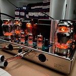
There are ALOT of extra B+ caps in there, did those replace the original quad caps, or were they added as an addition?
It looks like the choke was moved and put where the old quad cap was.
It might be an easy fix. I'm wondering what your B+ is before and after the added 6.8K that came with the octal kit?
Actually, I don't even see that in your photo, I see a huge green resistor that looks like the same one that was there before the mod.
Maybe with all those extra caps in there, the B+ is way over 550v, rather than the usual 500v or so that should be there.
The voltage to the board should be around 400v, which is what the 6.8K resistor is supposed to drop from the 500v.
So if you haven't got that in there, you need it. If you do have it in there, and you have 550v going to it instead of 500v,
then you'll need to use about 15K and about 5W resistor, maybe a couple of 27K or 30K 3w resistors in parallel.
Then you also may need to change the value of R39 to a smaller value like 1K so you have more negative bias available,
which will bring your bias voltage down. If your B+ is too high and your negative bias isn't negative enough,
you'll never get it to work correctly.
Roy Mottram- Admin
- Posts : 1839
Join date : 2008-11-30
here's the octal wiring diagram you should have gotten with your kit, as mentioned a couple of replys back
pjp3- Posts : 39
Join date : 2013-03-19
Age : 62
Location : Pelham, AL
Locally I can only find 30k 2 watt. The old green resistor is a 22k 3 watt
That brings the b+ down to 470 vdc. The capacitors are making 550 vdc.
I have 39k 2 watt resistors, would these further reduce the b+?
Also, what wattage are the 680ohm resistors?
That brings the b+ down to 470 vdc. The capacitors are making 550 vdc.
I have 39k 2 watt resistors, would these further reduce the b+?
Also, what wattage are the 680ohm resistors?
Roy Mottram- Admin
- Posts : 1839
Join date : 2008-11-30
what 680 ohm? The 6.8K is a 3w.
If you take your existing 22K and parallel a 39K across it, (ohms law) gives you 14K.
But you dont' want to reduce the resistance, as right now you've got too much voltage to the PCB.
I can't tell from the photo (it's a little mushy) but maybe that 22K was in there to knock the B+ down from 550v to 500v to start with.
Only you can see how you really have it wired. You may need to put that 22K back in there, and then from there,
put the 6.8K in series with the B+ connection to the circuit board.
The answer is in the drawing above, but that's assuming you have around 480v on pin 2 of the quad cap, which the 6.8K would drop to around 400v.
I also can't tell exactly where you choke connections are, on my diagram there would be on the quad cap at pin 1 and 2.
pjp3- Posts : 39
Join date : 2013-03-19
Age : 62
Location : Pelham, AL
I was wondering if I could replace the 22 with the 39 to further reduce the voltage.
I will try the 6.8K in series with the b+ to the board.
The 680 ohm I inquired about is the jumper on the output.
I will try the 6.8K in series with the b+ to the board.
The 680 ohm I inquired about is the jumper on the output.
pjp3- Posts : 39
Join date : 2013-03-19
Age : 62
Location : Pelham, AL
Ok, I have the right amp B+ down to 380 vdc, but the left amp will not drop below 470 vdc no matter how much resistance I put in line. Both amps run at 535 vdc. Any ideas?
Roy Mottram- Admin
- Posts : 1839
Join date : 2008-11-30
so figure out what's different between the two amps
pjp3- Posts : 39
Join date : 2013-03-19
Age : 62
Location : Pelham, AL
There are no differences. I put a 100k resistor in place of the 22k and that dropped the b+ to 420 at the board. If I put a 6.8k in series to the b+ it doesn't drop the voltage at all.
Roy Mottram- Admin
- Posts : 1839
Join date : 2008-11-30
seems like the one board is not pulling any current at all, so a bad connection or bad tube in there breaking the circuit flow
pjp3- Posts : 39
Join date : 2013-03-19
Age : 62
Location : Pelham, AL
Where does the ground for the pcb come from? Is it from the chassis or the power transformer?
Roy Mottram- Admin
- Posts : 1839
Join date : 2008-11-30
chassis ground, which is where the power transformer red-yellow wire is
|
|