The Dynaco Tube Audio Forum

Would you like to react to this message? Create an account in a few clicks or log in to continue.
The Dynaco Tube Audio Forum

Dedicated to the restoration and preservation of all original Dynaco tube audio equipment - Customer support for Tubes4hifi VTA tube amp and preamp kits and all Dynakitparts.com products


+9
chefothefuture
audiobill
buchela
peterh
BNR_1
Bob Latino
Roy Mottram
j beede
vtshopdog
13 posters

    New Build Questions

    WireNut
    WireNut


    Posts : 67
    Join date : 2017-02-21
    Location : Twin Cities

    New Build Questions - Page 2 Empty Re: New Build Questions

    Post by WireNut 24th April 2018, 7:04 pm

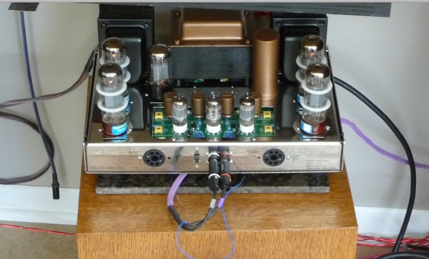
    The fuse is attached to the front of the fuse holder-like in the instructions (black, hot from the wall) and one black wire from the transformer is connected to the very back of the fuse holder; the switch is connected to the neutral (white) which runs via a wire to one post of the on/off switch, another wire runs back and is connected to the other black wire from the transformer, just like in the instructions only longer. It turns on and off just fine. The tubes glow and work just fine.
    I need to do the rest of the tests, but we had a sick dog today and my time has been limited.
    avatar
    audiobill


    Posts : 425
    Join date : 2014-03-13
    Location : Albany, NY

    New Build Questions - Page 2 Empty Re: New Build Questions

    Post by audiobill 24th April 2018, 7:39 pm

    Be careful, all your mods may do you in.
    vtshopdog
    vtshopdog


    Posts : 155
    Join date : 2015-07-11
    Location : UT, USA

    New Build Questions - Page 2 Empty Re: New Build Questions

    Post by vtshopdog 25th April 2018, 1:13 am

    A general electrical practice is for switches to be on the “inbound” hot lead rather than “outbound” neutral lead.  In this configuration anything “downstream “ of the switch will be have no voltage when power switch is in off position.
    WireNut
    WireNut


    Posts : 67
    Join date : 2017-02-21
    Location : Twin Cities

    New Build Questions - Page 2 Empty Re: New Build Questions

    Post by WireNut 25th April 2018, 7:35 am

    Shopdog, that is probably why I got a shock... I have changed hundreds of fuses while units were plugged in and never gotten a shock. (I worked for stereo stores in the golden age 70's & 80's where we had to do triage on all incoming service units)
    I will switch them around after everything is working on the unit- when I put in a perdy on/off switch.
    Thanks for the good tip!
    deepee99
    deepee99


    Posts : 2244
    Join date : 2012-05-23
    Location : Wallace, Idaho

    New Build Questions - Page 2 Empty Re: New Build Questions

    Post by deepee99 25th April 2018, 8:05 am

    audiobill wrote:Be careful, all your mods may do you in.
    Amen.
    WireNut
    WireNut


    Posts : 67
    Join date : 2017-02-21
    Location : Twin Cities

    New Build Questions - Page 2 Empty Re: New Build Questions

    Post by WireNut 25th April 2018, 8:46 am

    I think I actually only have one modification, that would be the LED bias readout, I do however have several upgrades that were installed exactly in the same way the stock stuff would have been.
    I have different caps, different pure copper wire to the board, EAR damping feet, ETI RCA & 5 way connectors... but other than that it is hooked up the same way as the instructions call for.
    Oh, I drilled more holes in the bottom for air flow & put a little damping material on the chassis and bottom, which I guess is sort of a mod.
    Think of it this way, some guys opt for the larger electrolyte and Russian caps- that is not called a mod.
    I have my favorite wire, caps, and connectors, I like the tried and proven sound of this stuff. I used the same stuff in my Nelson Pass amp and preamp, except I used better bypass caps in those. These bypass caps are the Cornell Dubler that Tony Gee loves so much, I thought I would give them a spin.
    WireNut
    WireNut


    Posts : 67
    Join date : 2017-02-21
    Location : Twin Cities

    New Build Questions - Page 2 Empty Re: New Build Questions

    Post by WireNut 27th April 2018, 2:30 pm

    I found the issue with the meters but will try them later.
    I am going to fire up the unit but have taken the meter system out of the amp. My question is this, on the page with the instructions for installing the driver board item # 4 talks about bending the pins and installing the socket in the amp, but I can't find how to connect the power tubes to those sockets to be able to test bias. Could someone tell me how to do it "the right way"?
    avatar
    audiobill


    Posts : 425
    Join date : 2014-03-13
    Location : Albany, NY

    New Build Questions - Page 2 Empty Re: New Build Questions

    Post by audiobill 27th April 2018, 2:39 pm

    Please recheck your instructions - it's in there.  

    Pin 8 of the "bias socket" is wired to pins 1 and 8 (lead goes through both) of the front output tube  socket (V3) ; pin 4 of the "bias socket" to pins 1 and 8 of the rear output tube socket (V2).

    Same deal on other side. See the purple wires in the illustration above.

    You may wish to remove all unused pins from the "bias sockets" to make things go easier and reduce possibility of shorts from those pins.


    Last edited by audiobill on 27th April 2018, 2:42 pm; edited 1 time in total
    WireNut
    WireNut


    Posts : 67
    Join date : 2017-02-21
    Location : Twin Cities

    New Build Questions - Page 2 Empty Re: New Build Questions

    Post by WireNut 27th April 2018, 2:42 pm

    Good advice on the pins, I like a "tight ship"
    Thanks a bunch
    avatar
    chefothefuture


    Posts : 28
    Join date : 2018-03-28

    New Build Questions - Page 2 Empty Re: New Build Questions

    Post by chefothefuture 27th April 2018, 3:25 pm

    If you're referring to the octal sockets on the front of the chassis for bias test points, just ditch them and get the bias test point mod from Roy at tubes4hifi. No extra pins and clean appearance inside and out. You can find them on this page http://www.tubes4hifi.com/MK3.htm
    avatar
    BNR_1


    Posts : 111
    Join date : 2013-06-11

    New Build Questions - Page 2 Empty Re: New Build Questions

    Post by BNR_1 27th April 2018, 3:34 pm

    buchela wrote:BNR :
    Why the fuse have to be before the switch ?, what am I missing

    Sorry for the late reply, but to your question. Generally speaking, you want the fuse to blow and de-energize anything downstream of the fault. If the fuse was located downstream of the switch and by purely bad luck the switch dead faults to the chassis the fuse may not blow since the path of least resistance is across the fault. The main service breaker may trip but it may not be quick enough if you are in contact with the chassis.
    Bob Latino
    Bob Latino
    Admin


    Posts : 3262
    Join date : 2008-11-26
    Location : Massachusetts

    New Build Questions - Page 2 Empty Re: New Build Questions

    Post by Bob Latino 27th April 2018, 5:26 pm

    WireNut wrote:I found the issue with the meters but will try them later.
    I am going to fire up the unit but have taken the meter system out of the amp. My question is this, on the page with the instructions for installing the driver board item # 4 talks about bending the pins and installing the socket in the amp, but I can't find how to connect the power tubes to those sockets to be able to test bias. Could someone tell me how to do it "the right way"?

    On Page #8 the manual the instructions tell you to ...

    "31. Obtain the last two tube sockets that will be installed in the two power take off holes in the front of the chassis. DO NOT INSTALL THEM AT THIS TIME. Hold the socket with the back facing you and the keyway pointing to the LEFT. Connect one end of a 6 inch wire to pin #8 (S) of one of the sockets and run the wire to the LEFT of the socket as viewed from the BACK of the socket. Connect one end of an 8 1/2 inch wire to pin #4 (S) of this socket and run this wire to the LEFT also. Place this socket with the two wires attached aside. This will be installed in the LEFT power takeoff socket later.

    32. Repeat step 31 for the other remaining tube socket (the keyway again faces to the LEFT as viewed from the back) except run the wires to the RIGHT. This socket will become the RIGHT power take off socket. Neither of these two sockets will be used for any “power take off” but two pins on each tube socket will be used to measure bias on the four output tubes."


    Later step # 4 on page 9 the instructions tell you to ..

    4. Obtain the two tube sockets that will fit into the power take off holes in the front of the chassis. Bend the tube socket pins in against the back of the tube socket. Bend them TOWARDS THE OUTER RIM of the tube socket. Bend towards the BACK of the amp slightly (if necessary) the two front .22 Mfd coupling capacitors (or the two front Russian PIO caps if you have the Russian PIO upgrade caps) on the driver board to gain some clearance. Install the LEFT power takeoff socket with 4-40 hardware. Install the RIGHT power take off socket with 4-40 hardware. Both are a tight fit but will go in to their respective holes.

    Later on steps 7 -10 on page 10 the instructions tell you to ..

    7. Remove 5/8 inch of insulation from the wire coming from pin #8 of the LEFT power takeoff. Run this wire to V3. Slide the wire through pin # 1 (S) and into pin #8. You may have to twist either or both pins slightly to line up the solder attachment holes. Attach one end of a 10 ohm 2 watt bias resistor to pin #8 of V3 (S). Connect the OTHER end of the 10 ohm 2 watt resistor to the GROUND LUG that faces pin 8 (S).

    8. Remove 5/8 inch of insulation from the wire coming from pin #4 of the LEFT power takeoff. Run this wire to V2. Slide the wire through pin # 1 (S) and into pin #8. You may have to twist either or both pins slightly to line up the solder attachment holes. Attach one end of a 10 ohm 2 watt bias resistor to pin #8 of V2 (S). Connect the OTHER end of the 10 ohm 2 watt resistor to the GROUND LUG that faces pin 8 (S).

    9. Remove 5/8 inch of insulation from the wire coming from pin #8 of the RIGHT power takeoff. Run this wire to V6. Slide the wire through pin # 1 (S) and into pin #8. You may have to twist either or both pins slightly to line up the solder attachment holes. Attach one end of a 10 ohm 2 watt bias resistor to pin #8 of V6 (S). Connect the OTHER end of the 10 ohm 2 watt resistor to the GROUND LUG that faces pin 8 (S).

    10. Remove 5/8 inch of insulation from the wire coming from pin #4 of the RIGHT power takeoff. Run this wire to V7. Slide the wire through pin # 1 (S) and into pin #8. You may have to twist either or both pins slightly to line up the solder attachment holes. Attach one end of a 10 ohm 2 watt bias resistor to pin #8 of V7 (S). Connect the OTHER end of the 10 ohm 2 watt resistor to the GROUND LUG that faces pin 8 (S).

    Bob


    deepee99
    deepee99


    Posts : 2244
    Join date : 2012-05-23
    Location : Wallace, Idaho

    New Build Questions - Page 2 Empty Re: New Build Questions

    Post by deepee99 27th April 2018, 5:40 pm

    Guys, when are you ever going to learn? All the expensive tubes, caps, switches and resistors we buy exist for a single reason: to protect the 15-cent fuse from blowing.
    vtshopdog
    vtshopdog


    Posts : 155
    Join date : 2015-07-11
    Location : UT, USA

    New Build Questions - Page 2 Empty Re: New Build Questions

    Post by vtshopdog 27th April 2018, 7:18 pm

    deepee99 wrote:Guys, when are you ever going to learn? All the expensive tubes, caps, switches and resistors we buy exist for a single reason: to protect the 15-cent fuse from blowing.

    Whuuut?  

    You don’t use Rhodium audiophile grade fuses? They cost 47x more than regular fuses and therefore improve soundstage and resolution 500%. .....
    deepee99
    deepee99


    Posts : 2244
    Join date : 2012-05-23
    Location : Wallace, Idaho

    New Build Questions - Page 2 Empty Re: New Build Questions

    Post by deepee99 27th April 2018, 11:56 pm

    vtshopdog wrote:
    deepee99 wrote:Guys, when are you ever going to learn? All the expensive tubes, caps, switches and resistors we buy exist for a single reason: to protect the 15-cent fuse from blowing.

    Whuuut?  

    You don’t use Rhodium audiophile grade fuses? They cost 47x more than regular fuses and therefore improve soundstage and resolution 500%. .....
    No, shopdog, I prefer plutonium over rhodium, although any PGM is good. Plutonium delivers better dynamic range, far less THD and utters a more fluid signal. I have ordered some and it is slated to arrive from Pluto about seven years from now and may have some extra for sale. I know the chief engineer on the Pluto rocket shot. Sadly, they found no unobtanium inside the known solar system or the Kuiber Belt.
    WireNut
    WireNut


    Posts : 67
    Join date : 2017-02-21
    Location : Twin Cities

    New Build Questions - Page 2 Empty Re: New Build Questions

    Post by WireNut 28th April 2018, 9:44 am

    I got it hooked up as advised and have an anomaly, the left side reads in the 30's and the right side reads as it is supposed to (like .4) ... any ideas?
    BTW- that is not what my page 10 looks like and I do not have that part in my instructions pertaining to the sockets on the front.
    Roy Mottram
    Roy Mottram
    Admin


    Posts : 1839
    Join date : 2008-11-30

    New Build Questions - Page 2 Empty Re: New Build Questions

    Post by Roy Mottram 28th April 2018, 7:15 pm

    wow, I get a headache just reading more than 2 paragraphs of step-by-step, I'm a visual guy, that's why I just refer to the diagram I posted on post 9 of this thread.
    Truely, one photo is worth a thousand words.
    avatar
    chefothefuture


    Posts : 28
    Join date : 2018-03-28

    New Build Questions - Page 2 Empty Re: New Build Questions

    Post by chefothefuture 28th April 2018, 9:11 pm

    tubes4hifi wrote:wow, I get a headache just reading more than 2 paragraphs of step-by-step, I'm a visual guy, that's why I just refer to the diagram I posted on post 9 of this thread.
    Truely, one photo is worth a thousand words.

    The bias test jack upgrade that I bought from you is way better than messing with the tube sockets. Cleaner inside and out.
    WireNut
    WireNut


    Posts : 67
    Join date : 2017-02-21
    Location : Twin Cities

    New Build Questions - Page 2 Empty Re: New Build Questions

    Post by WireNut 29th April 2018, 9:14 am

    I found the issue, it was with wiring when I took out the LED meters. It is up and working now- burning in.
    I will reinstall the meters and put in a new on/off switch later... I am just really happy it is working.
    Here is what it looks like (I made a special interconnect for it):

    New Build Questions - Page 2 F221a80f09d6b6b951d39b388e6e2021
    deepee99
    deepee99


    Posts : 2244
    Join date : 2012-05-23
    Location : Wallace, Idaho

    New Build Questions - Page 2 Empty Re: New Build Questions

    Post by deepee99 29th April 2018, 4:34 pm

    Pretty lookin' build there, WireNut.
    WireNut
    WireNut


    Posts : 67
    Join date : 2017-02-21
    Location : Twin Cities

    New Build Questions - Page 2 Empty Re: New Build Questions

    Post by WireNut 29th April 2018, 4:41 pm

    Thanks, it sounds pretty good for just a couple of hours play. I expect it to be wonderful by Friday!
    deepee99
    deepee99


    Posts : 2244
    Join date : 2012-05-23
    Location : Wallace, Idaho

    New Build Questions - Page 2 Empty Re: New Build Questions

    Post by deepee99 29th April 2018, 5:07 pm

    WireNut wrote:Thanks, it sounds pretty good for just a couple of hours play. I expect it to be wonderful by Friday!
    Give it at least 100 hours while the tubes and caps burn in. All of a sudden, it will sparkle beyond belief.
    WireNut
    WireNut


    Posts : 67
    Join date : 2017-02-21
    Location : Twin Cities

    New Build Questions - Page 2 Empty Re: New Build Questions

    Post by WireNut 2nd May 2018, 8:24 am

    Guys,
    The amp was on for three days and was sounding better and better! Last night after I went to bed I heard a loud "crackle" sound like a small meteorite had hit the house & it blew the fuse.
    The first thing I did this morning is get out my trusty Mighty Mite and tested the NOS Mullard fat base rectifier and it was good. Does anyone have a good guess what that might have been?
    Thanks!
    avatar
    audiobill


    Posts : 425
    Join date : 2014-03-13
    Location : Albany, NY

    New Build Questions - Page 2 Empty Re: New Build Questions

    Post by audiobill 2nd May 2018, 8:44 am

    Your fuse is blowing because either your transformer primary winding connections are somehow shorting or too much current is being pulled through the secondary windings.

    Assuming the latter, it is unlikely your rectifier tube is undamaged, but here are some things to check

    With amp off and unplugged, measure resistance to ground of each lug of the quad cap, should be in the hundreds of ohms range,

    Check the capacitance of each quad cap lug to ground - should measure about 220 uf except the lug that connects to the board, about 70uf here,

    Look carefully at the base of the quad cap for any solder bridges from lugs to chassis

    Look carefully all the way around the board, from the top, to insure no possible shorts from component or wire leads to chassis,

    Test with scm disconnected if no problems with the above , capacitance values above will be different
    WireNut
    WireNut


    Posts : 67
    Join date : 2017-02-21
    Location : Twin Cities

    New Build Questions - Page 2 Empty Re: New Build Questions

    Post by WireNut 2nd May 2018, 10:58 am

    Bill, I will do as you suggest... but why would it take three days of continuous play to get to the point of blowing a fuse? What would that noise have been?
    Thanks!

    Sponsored content


    New Build Questions - Page 2 Empty Re: New Build Questions

    Post by Sponsored content


      Current date/time is 26th April 2024, 10:59 am