Hi all, first time posting here. I was looking for a forum dedicated to Dynaco and this seems to be the one.
I'm not one for long intro's so I'll jump right into it. I purchased a used ST-70 MKII and I have some questions and possibly, concerns. Right off the bat, the amp works. It sounds good so I don't see any issue there. It came with JJ's as spares (used) and Mullards in the amp.
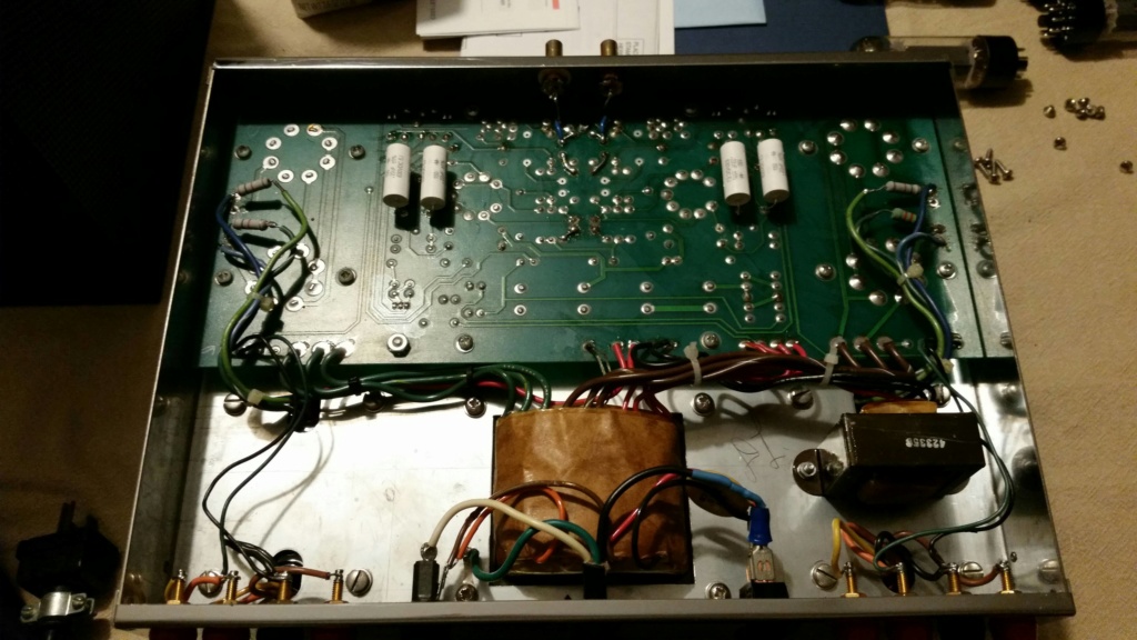
I'm not afraid to check out what hardware is under the skirt so it didn't take long to take off the top cover and the bottom as well and this is where I found a few things that were questionable.
1. The back of the amp is labeled for 220v, no mention of 120v? Also, the fuse is labeled as "1.5 amp slo-blo" however, it's got a 3A 250 installed. Not sure what to make of those.
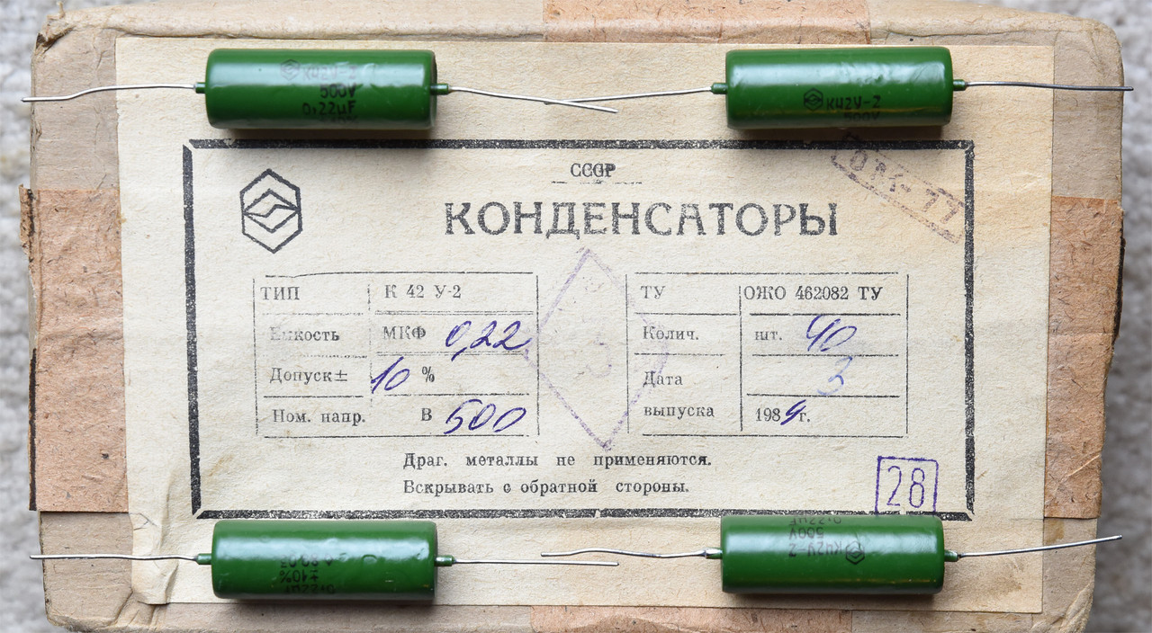
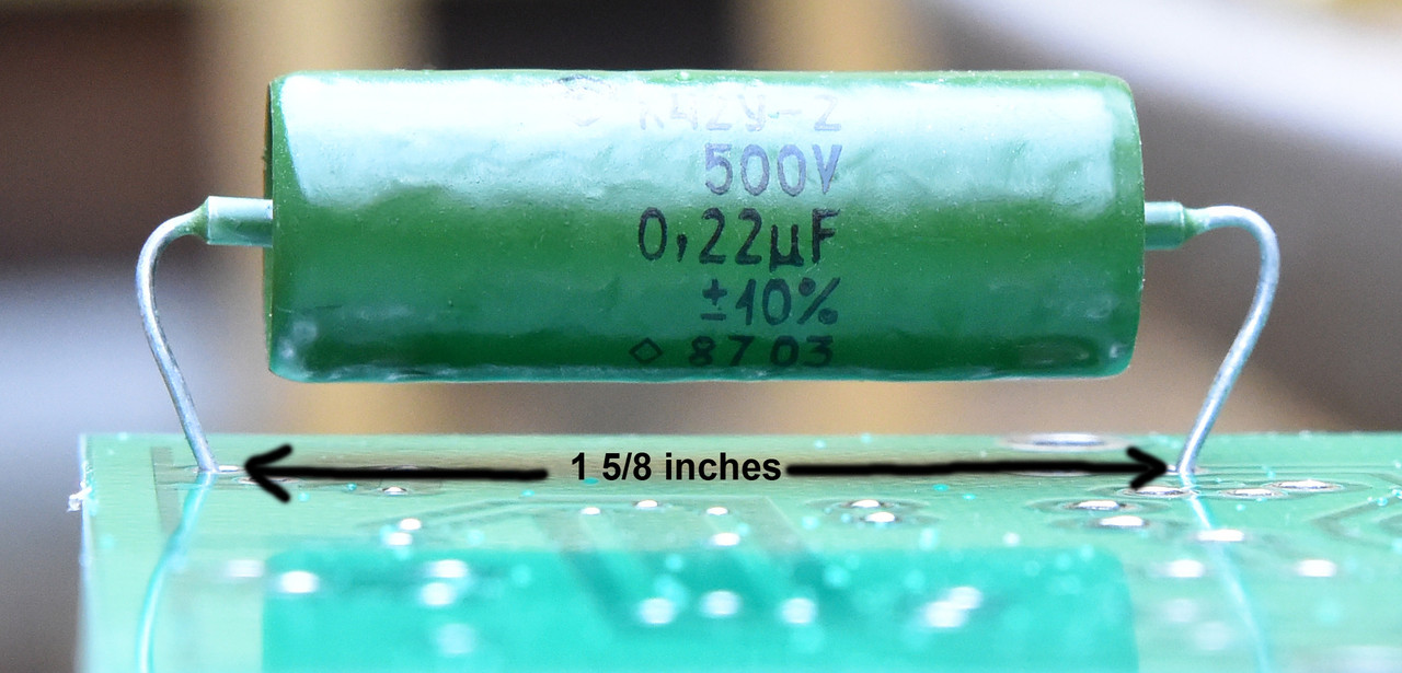
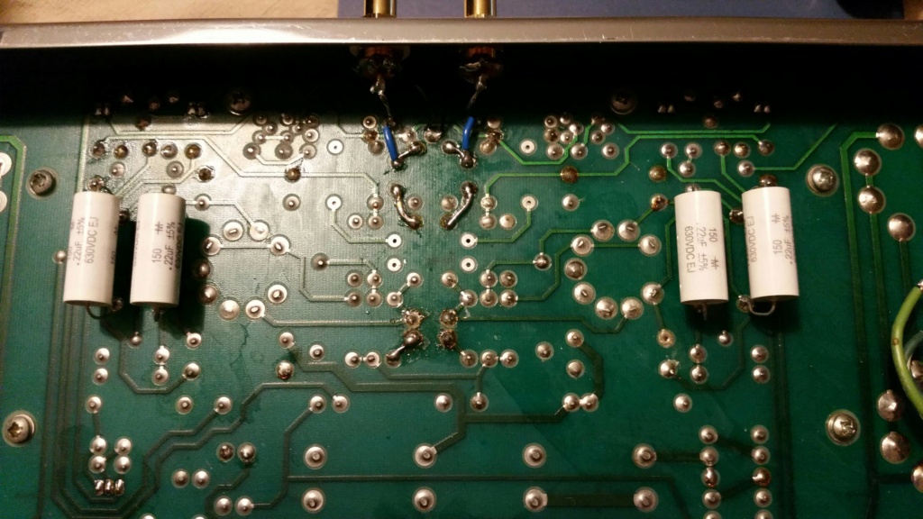
2. After taking the top cover off, I noticed two things. Capacitors C25, C26, C15 and C16 were soldered on the bottom of the PCB. Looking at the original schematic, the best I can make out for those caps is .68uf 400v? What was installed instead are .22uF 630v?
3. C21 and C11 were replaced as well with Russian caps. The specified values should be .18uF 50v and what's installed is 0.047uF and no V value.
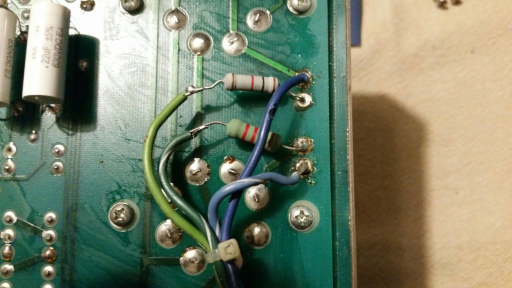
4. There are several jumpers that were installed on the underside. They look rather ugly and I would care to fix those as well but am curious to know if they were factory and why were they added?
5. Can the 6GHBA tubes be changed out for any other tube? Just curious.
That's all I have off the top of my mind. Who ever did the butchering on this amp with their custom trimmings hasn't has much time behind an iron, the work is sloppy. Butchered at best. The solder isn't even fully adhered on some caps. The factory work looks good.
I will be replacing the power cord as well. Looks like someone tried to fix it in the past, there is a replacement plug on it. There was an attempt to remove the cord from the case which completely damaged the train relief so that's gotta get fixed.
Over all, I am happy with the amp. It is certainly in good condition. No rust at all and the cover is excellent at well. I would love to hear some input from your guys. Should I keep the caps that were installed or return them to original values? Anything else I can change out to improve the circuitry? There are some components that looks like they were slapped in there carelessly that I can rework. I am an anal bastard when it comes to soldering. I am in the process of building the Engineers Amp using TV sweep tubes if anyone cares to take a look, ill drop the link to that thread -apparently, I can't drop external links. Please go to diyaudio.com and search Build Log: P Millett's DCPP "Engineer's Amp". I am "M3Roc" on that thread.
Please take a look at the pics I've included of the ST-70 for reference. I can't leave an external link so ill try to upload all the pics here.
I'm not one for long intro's so I'll jump right into it. I purchased a used ST-70 MKII and I have some questions and possibly, concerns. Right off the bat, the amp works. It sounds good so I don't see any issue there. It came with JJ's as spares (used) and Mullards in the amp.
I'm not afraid to check out what hardware is under the skirt so it didn't take long to take off the top cover and the bottom as well and this is where I found a few things that were questionable.
1. The back of the amp is labeled for 220v, no mention of 120v? Also, the fuse is labeled as "1.5 amp slo-blo" however, it's got a 3A 250 installed. Not sure what to make of those.
2. After taking the top cover off, I noticed two things. Capacitors C25, C26, C15 and C16 were soldered on the bottom of the PCB. Looking at the original schematic, the best I can make out for those caps is .68uf 400v? What was installed instead are .22uF 630v?
3. C21 and C11 were replaced as well with Russian caps. The specified values should be .18uF 50v and what's installed is 0.047uF and no V value.
4. There are several jumpers that were installed on the underside. They look rather ugly and I would care to fix those as well but am curious to know if they were factory and why were they added?
5. Can the 6GHBA tubes be changed out for any other tube? Just curious.
That's all I have off the top of my mind. Who ever did the butchering on this amp with their custom trimmings hasn't has much time behind an iron, the work is sloppy. Butchered at best. The solder isn't even fully adhered on some caps. The factory work looks good.
I will be replacing the power cord as well. Looks like someone tried to fix it in the past, there is a replacement plug on it. There was an attempt to remove the cord from the case which completely damaged the train relief so that's gotta get fixed.
Over all, I am happy with the amp. It is certainly in good condition. No rust at all and the cover is excellent at well. I would love to hear some input from your guys. Should I keep the caps that were installed or return them to original values? Anything else I can change out to improve the circuitry? There are some components that looks like they were slapped in there carelessly that I can rework. I am an anal bastard when it comes to soldering. I am in the process of building the Engineers Amp using TV sweep tubes if anyone cares to take a look, ill drop the link to that thread -apparently, I can't drop external links. Please go to diyaudio.com and search Build Log: P Millett's DCPP "Engineer's Amp". I am "M3Roc" on that thread.
Please take a look at the pics I've included of the ST-70 for reference. I can't leave an external link so ill try to upload all the pics here.
Last edited by Tiny Anakim on Sat Nov 17, 2018 8:53 pm; edited 1 time in total