

Unless you live in Minnasoda! Oofda!audiobill wrote:You don't need insulation on legs....
+9
Roy Mottram
deepee99
StevieRay
arledgsc
cci1492
audiobill
Peter W.
WLT
bbqjoe
13 posters
I let the smoke out.

bbqjoe- Posts : 98
Join date : 2018-12-03

Bob Latino- Admin
- Posts : 3262
Join date : 2008-11-26
Location : Massachusetts
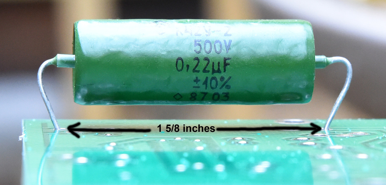
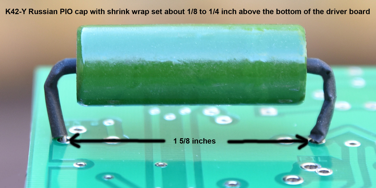
I discussed this with Roy a couple of days ago .. If you set the Russian K42-Y PIO caps as below (first photo) you don't really need the shrink tubing around the two leads. Set UP like this, the caps will be about 1/4 of an inch above the board and the leads should not be able to touch anything on the board. Now - Considering that the inner lead does have about 275 VDC and the outer lead about -40 to -50 VDC what I am going to do is include shrink tubing on all future Russian PIO caps as seen in the SECOND photo. The second photo shows the installation of the two leads with the black shrink tubing. After the cap is installed you can use a hair dryer to shrink the tubing around the lead.
Bob
Bob

audiobill- Posts : 425
Join date : 2014-03-13
Location : Albany, NY
With the insulation, be sure to solder carefully so there is good contact to the board. I like to sand the leads a little before soldering to be sure there is.
New2Tubez- Posts : 184
Join date : 2018-03-20
Location : NY
When I'm more clear on the AB board, I'll replace my K-40Y's with the longer, thinner K-42Y's.
I put clear heat shrink on the 42's so the values could still be read. I'll heat shrink the leads when I do the install.

I put clear heat shrink on the 42's so the values could still be read. I'll heat shrink the leads when I do the install.

billinrio- Posts : 107
Join date : 2018-01-03
bbqjoe wrote:
Anyways, here's where my problem was.
I broke the wire going to the switch while tying everything up.
It arced between the switch and the resistor.
Resistor was fried, not to mention the switch.


The place in your initial post where you say you replaced the original switch with a toggle switch did raise a red flag for me.
bbqjoe- Posts : 98
Join date : 2018-12-03
It's just as simple as a switch can be.billinrio wrote:
The place in your initial post where you say you replaced the original switch with a toggle switch did raise a red flag for me.
I found the slider switch could be slid, and not make proper contact consistently. Toggles just don't behave like that.
pichacker- Posts : 103
Join date : 2016-08-01
Age : 59
Location : Near to London - UK
The other thing to consider with the triode/pentode switches are the peak voltages present on them under running conditions. Differential between the two halves you could have almost 2xHT voltage. A good quality switch should be used here.
bbqjoe- Posts : 98
Join date : 2018-12-03
pichacker wrote:The other thing to consider with the triode/pentode switches are the peak voltages present on them under running conditions. Differential between the two halves you could have almost 2xHT voltage. A good quality switch should be used here.
The switches used for triode/pentode switching are the ones Bob provides with the kit.

deepee99- Posts : 2244
Join date : 2012-05-23
Location : Wallace, Idaho
Those switches, beefy as they are, should only be toggled with the amp(s) off or no signal input to avoid Pichacker's scenario.bbqjoe wrote:pichacker wrote:The other thing to consider with the triode/pentode switches are the peak voltages present on them under running conditions. Differential between the two halves you could have almost 2xHT voltage. A good quality switch should be used here.
The switches used for triode/pentode switching are the ones Bob provides with the kit.
bbqjoe- Posts : 98
Join date : 2018-12-03
deepee99 wrote:Those switches, beefy as they are, should only be toggled with the amp(s) off or no signal input to avoid Pichacker's scenario.bbqjoe wrote:pichacker wrote:The other thing to consider with the triode/pentode switches are the peak voltages present on them under running conditions. Differential between the two halves you could have almost 2xHT voltage. A good quality switch should be used here.
The switches used for triode/pentode switching are the ones Bob provides with the kit.
I wouldn't go so far as to call them beefy, seeing as they probably fall into the micro switch category.
So far, I'm not in the habit of switching back and forth.
Bob states it's OK to switch as long as the amp isn't cranked up.
Since he is the kit designer, I have faith in him that he didn't cut corners and use something outside of tolerances, but I certainly could see using a chunkier switch where as much as 500 volts is concerned.
bbqjoe- Posts : 98
Join date : 2018-12-03
I don't think I'll ever get over this, I'm permanently scarred.
The shorting happened right after the click of the relay on the time delay board.
Ever since the accident and repair, everything has been fine.
But every time I turn the amp on, I wait for the click, and cringe in fear of snap crackle pop!
The shorting happened right after the click of the relay on the time delay board.
Ever since the accident and repair, everything has been fine.
But every time I turn the amp on, I wait for the click, and cringe in fear of snap crackle pop!
Similar topics
|
|
|