by pichacker Mon Jul 15, 2019 2:52 am
Ref …
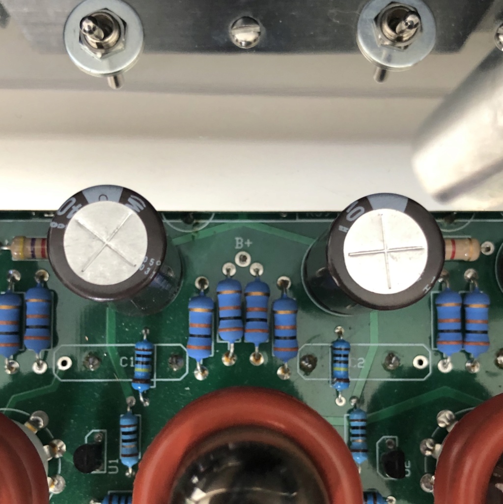
https://dynacotubeaudio.forumotion.com/t4141-latino-st120-with-vta-sp9-ph12What's the deal with the extra 3k9/390R? resistor and diodes across the HT rectifier on your amp Kray? Sort of hidden SS rectifier setup. Not quite a "yellow Sheet" modification where the diodes are located.
Also assume that the large wire wound resistor on the quad cap feeds the front displays. Could this be pulling down the HT voltage you are measuring? All depends if its prior or post the dropper resistor on the quad cap. Not too clear from the photo.
If this is suppling the front meters and is dropping the full HT (550v) down to 12v through 25k then this is running at maximum dissipation if a 10w component. ((500 * 500) / 25000) = 10W. A lot of wasted power in heat.
VERY CAREFULLY Check the HT at the quad cap with the two linked pins or the gold banded end (towards the rear) of the extra resistor on the tag strip with the red wires. Only one hand at a time near the amp when you're doing this and the other behind your back!
I'd also be wary of upping the supply voltage too far as you'll risk overrunning the tube filaments not to mention sky rocketing the main HT.
On a side note I wonder if twisting the cathode and grid wires together from the AB board has any effect? Fortunately both lines are relatively low impedance. Looks like the original amplifier was fairly neatly built and then the "meter" guy got involved

For the driver board on my amp I too have a voltage slightly lower than spec and this is measured after the dropper resistor on the quad cap. Makes little difference. But... if it's working ok and you're enjoying the sound why not leave alone and stop worrying..

Steve