The Dynaco Tube Audio Forum

Would you like to react to this message? Create an account in a few clicks or log in to continue.
The Dynaco Tube Audio Forum

Dedicated to the restoration and preservation of all original Dynaco tube audio equipment - Customer support for Tubes4hifi VTA tube amp and preamp kits and all Dynakitparts.com products


5 posters

    Setting the gain on an ST-70

    avatar
    dcboucher


    Posts : 6
    Join date : 2021-01-11

    Setting the gain on an ST-70 Empty Setting the gain on an ST-70

    Post by dcboucher Tue Jan 12, 2021 6:43 pm

    Hey everybody!  I'm new here, but I've been an ST-70 owner for years and reading the posts has been nothing short of enlightening.

    I've got a new setup that requires having gain trims at the power side of the equation and I'm wondering about the best way to match gains on the two channels of my ST-70.  They aren't miles off ~ 1-2 dB.  The gain difference doesn't follow the 7199 tubes or the EL34's.  I'm considering just replacing all of the resistors as they are old carbon comps.  I just thought I might put trimmers in somewhere to get it as tight as possible and adjust for variation in the tubes.

    The filter caps have been replaced by an SDS board underneath (long ago by a previous owner).

    Thanks,

    -d

    Setting the gain on an ST-70 Img_5710
    Bob Latino
    Bob Latino
    Admin


    Posts : 3263
    Join date : 2008-11-26
    Location : Massachusetts

    Setting the gain on an ST-70 Empty Re: Setting the gain on an ST-70

    Post by Bob Latino Tue Jan 12, 2021 7:12 pm

    Setting the gain on an ST-70 PC-3driverboardfront-laterversionco

    Two critical resistors on the original Dynaco ST-70 driver board that affect gain are the two 1000 ohm resistors seen in the middle of the driver board. These two resistors are in the feedback line - one 1000 ohm resistor is on each channel. If these two resistors do change their value, then the gain of the amp will be off from channel to channel. Dynaco used relatively small "feedback resistors" here which allows the amp to have a lot of feedback (about 20 dB) which lowers the gain of the amp.

    IMHO > rather than change out all the resistors on this board, you should just buy a new board and parts set from Dynakitparts. The Dynaco ST-70 amp came out in 1959 and some of these amps are now 62 years old and can have a host of other minor problems that can show up like loose tube socket pins, chokes that leak out a "tan goo" out onto the bottom cover and of course those carbon composition resistors that have strayed from their actual value (usually in an upward direction)

    Bob
    avatar
    dcboucher


    Posts : 6
    Join date : 2021-01-11

    Setting the gain on an ST-70 Empty Re: Setting the gain on an ST-70

    Post by dcboucher Tue Jan 12, 2021 8:33 pm

    Thanks so much Bob!

    I'm going to order a new board. In the meantime, I pulled the carbon comps out and they are off by about 200 ohms. I have some 1% 1K metal film resistors on hand. Is 1/2 watt enough?

    -d
    Bob Latino
    Bob Latino
    Admin


    Posts : 3263
    Join date : 2008-11-26
    Location : Massachusetts

    Setting the gain on an ST-70 Empty Re: Setting the gain on an ST-70

    Post by Bob Latino Tue Jan 12, 2021 8:44 pm

    dcboucher wrote:Thanks so much Bob!

    I'm going to order a new board.  In the meantime, I pulled the carbon comps out and they are off by about 200 ohms.  I have some 1% 1K metal film resistors on hand.  Is 1/2 watt enough?

    -d

    You could try a 1/2 watt resistor in there but I think that the resistors in there now are 1 watt ?

    Bob
    avatar
    dcboucher


    Posts : 6
    Join date : 2021-01-11

    Setting the gain on an ST-70 Empty Re: Setting the gain on an ST-70

    Post by dcboucher Tue Jan 12, 2021 10:04 pm

    The 1/2 watters have been in there cooking for an hour and they seem to be fine. I don't really measure much of a voltage drop across them. The channels are now 0.58 dB different, which is better -- certainly good enough for now, until the new board and parts show up. I have to say that I am amazed by this amp every time I listen to it and in my measurements, it's razor flat from 20Hz - around 2K when it starts it's gentle descent, hitting -3dB around 18K. It's a little flatter up top on the 16 ohm tap. I run it in triode mode, which may be the cause of the roll-off. I don't really know.

    Anyway, thanks again. I'm glad to know you are out there.

    -d
    WLT
    WLT


    Posts : 186
    Join date : 2013-07-13
    Location : Rochester NY

    Setting the gain on an ST-70 Empty Re: Setting the gain on an ST-70

    Post by WLT Wed Jan 13, 2021 1:53 pm

    Bob always has great insight to the issues on Dynacos. I want to point out two more items.

    The 1000 ohm feedback resistor is critical but also must be looked at (see schematic) in relation to the 47 ohm resistor that is part of the pentode’s cathode resistor. The 1000 ohm and 47 ohm resistors together form a voltage divider that sets the dB of feedback. Not just the 1000 ohm resistor. These 47 ohm resistors will go out of spec to so some of your deviations may be from having them mismatched channel to channel.

    The plate and cathode resistors for the pentode voltage amplifier and the phase splitter section are also critical. The 620 ohm cathode resistor adds to the 47 ohm to ground to set the bias voltage. If that plate resistor is also off the gain of that tube will be hard to match to the other channel. It is tough enough to get the tubes to be consistent with each other but having these resistors out of spec is a sure way to not have channel balance.

    Many replace all the resistors with metal film as they have excellent tolerances. I like the carbon film types as they also can have great tolerances but still use carbon in their construction. Much is written about each type and either will help your channel balance out. If the unbalance persists you may have some tube or capacitor related problems.
    avatar
    dcboucher


    Posts : 6
    Join date : 2021-01-11

    Setting the gain on an ST-70 Empty Re: Setting the gain on an ST-70

    Post by dcboucher Wed Jan 13, 2021 2:44 pm

    Thank you very much, WLT!

    I hand matched new resistors in those positions and now the channels are 0.05 dB different with the dummy load! I'll do some listening throughout the day, but what a difference that made in the measurements. The 620's were close and the 47's were close, but the ratios were not as the 620 on one channel drifted high and its corresponding 47 drifted low, while the other channel was the opposite. That's a good lesson in circuit theory (the real reason I tinker anyway).

    I guess my last question is about bias set. Should I adhere to the 1.57V marked on the chassis? I've read a few places that that might be a bit hot and 1.4-1.5 might be more appropriate.

    Again, my thanks to you both!

    -d
    WLT
    WLT


    Posts : 186
    Join date : 2013-07-13
    Location : Rochester NY

    Setting the gain on an ST-70 Empty Re: Setting the gain on an ST-70

    Post by WLT Wed Jan 13, 2021 8:49 pm

    Search earlier posts here and you will find this discussed in detail.

    Advantage of leaving at 1.57VDC – High current thru output tubes. Sets the amp far into class A at idle. Will have the lowest measurable distortion.

    Disadvantage at 1.57 VDC – pushes output tubes hard which shortens their life. Not a problem in 1959 with output tubes costing $2-3 at the local drug store. Today tubes cost much more and no one likes to swap them on a regular basis. Turning down the output tube current helps and the minor amount of increased distortion seems to be inaudible.

    My system. An EL34 has a plate dissipation of 25 watts (depending on make etc.). Per much internet discussion use 70% of that for derating (think longevity). That number still gives good sound. My Dyna ST70 uses no isolation transformer or thermistors. Accordingly B+ is around 465 VDC. Watts = VxI. Solve for I = 25 x .7/465= 38mA. Many guys use 40 mA and that is reasonable. Two tubes share one 13.5 ohm resistor so V=IR = 2 x.04 x13.5= 1.08 VDC. If you want to use 1.2 or 1.3 VDC that is OK as well. Try several settings and see if you can hear a difference. This is a feel good number vs. cost of output tube replacement. No right or wrong answer. Others may disagree and I can understand most of their arguments.
    avatar
    dcboucher


    Posts : 6
    Join date : 2021-01-11

    Setting the gain on an ST-70 Empty Re: Setting the gain on an ST-70

    Post by dcboucher Wed Jan 13, 2021 9:16 pm

    Lowest THD (measured with my Minilyzer) on my system yields 1.45V at the bias checkpoint. I'm going to live with that until I do a full rebuild.

    Also, one quick question: I think I have a 15.6 Ohm resistor, making the calculation 2 tubes x .04 Amps x 15.6 = 1.25VDC. Is that correct?

    OK, really last question...I feel like I should take out the mono/stereo switch. It just seems like more room for sonic imbalance, regardless of the quality of the soldering or components. Am I dreaming?

    This is my last day of tinkering before I have to get real work done, but it's been a good one and an educational one. I thank you all.

    -d
    WLT
    WLT


    Posts : 186
    Join date : 2013-07-13
    Location : Rochester NY

    Setting the gain on an ST-70 Empty Re: Setting the gain on an ST-70

    Post by WLT Thu Jan 14, 2021 9:50 am

    My bad. You are right about the 15.6 ohm resistor. I had the MK IV schematic up which uses 13.5 ohm. Same number crunching so 1.25 VDC or so is the right calculation. Your 1.45 VDC is fine. Try listening to slightly lower settings and see if you can hear a difference. I doubt it. Actual distortion readings can be reassuring as well.

    My vintage ST 70 is playing now and sounds great. Enjoy

    avatar
    Solder Slinger


    Posts : 36
    Join date : 2009-05-24

    Setting the gain on an ST-70 Empty A couple of suggestions

    Post by Solder Slinger Thu Jan 21, 2021 12:49 pm

    Hi dcboucher,

    A couple of other suggestions:

    Robert Tomer, a 1950s "tube guru" suggested that adding an NTC (Negative Temperature Coefficient varistor, CL-80 (3 amp rated) is the part # I believe) to the 117 vac power supply leads would extend the tube heater life 4X by creating a slow turn-on for the tube heaters (as well as being easier on the rest of the amp). This also will lower the voltage seen by the amp a volt or 2. The current 121-124 VAC supplied by our modern power company is somewhat higher than what the amp was designed for and this will help lower that voltage a bit. You could also use (2) CL-90s (2 amp rated) in parallel to slow down the turn-on even more as well as dropping the voltage a bit more. I put mine on the hot (black) lead of the power cord.

    Secondly, biasing the amp at 1.45 volts is good, I'd run it at 1.25 volts but YMMV... but please check the biasing resistors; the 15.6 ohm carbon comp resistors used to measure the feedback voltage off pin 8 of the output tubes may have drifted over time. Using a pair of metal film resistors to make up a new 15.6 ohm value will work but I prefer to use a 1 ohm, 1% or 1/2% resistor, which when using a meter set to mV range will give you the actual combined cathode currents in mA. This also lowers the internal impedance of the amp giving it a faster, snappier sound. Easy enough that you can experiment with this if you want. You might also want to add the individual tube bias adjustment kit from DynaKit Parts to better match the tube currents.

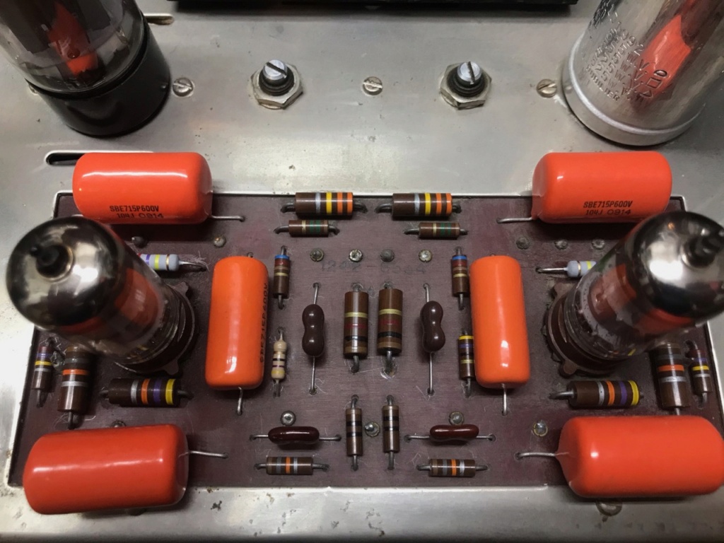
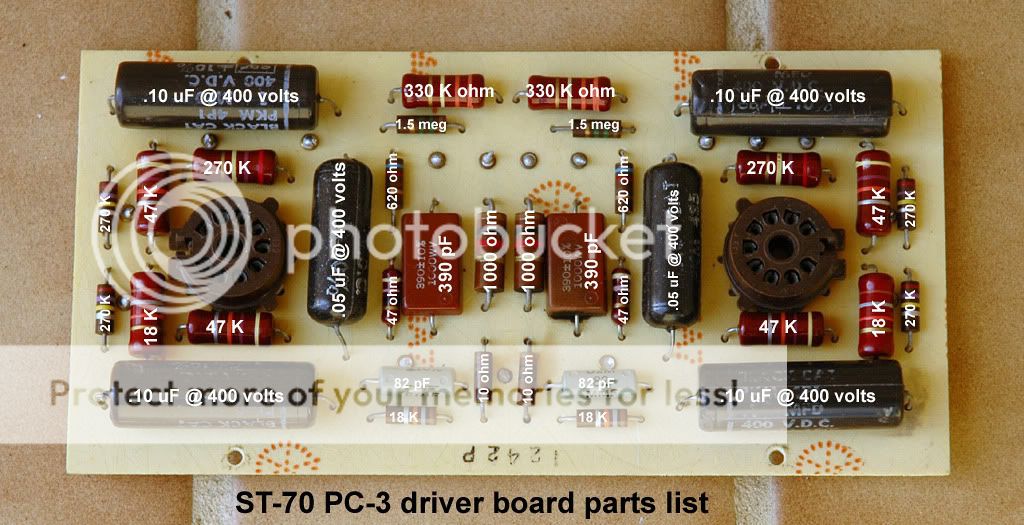
    Regarding feedback, there are two parts to the feedback circuit on the ST-70, a 390 pf cap (marked mmf on schematic) from the primary ultralinear tap side of the output transformer and the 1K resistor from the 16 ohm tap of the secondary side. I run my ST-70 with no feedback, if you want feedback, try moving the feedback tap to the 4 or 8 ohm taps depending the impedance of the speakers you are using and doubling the resistance each time you move the tap down. You might also experiment with increasing the feedback resistor even more to reduce feedback.

    My ST-70 isn't typical, I use a Triode Electronics driver board, somewhat modified, a Triode Electronic power transformer and an SDS cap board plus about another 700 mfd of caps, solid state diodes and a time delay on the high voltage. I have the bias set up so I can run EL34s, 6550s, KT90s or KT120s in my amp with 10 turn, 25K pots, usually use KT-90s as they sound very good and offer a little more clearance between the tubes for better air circulation.

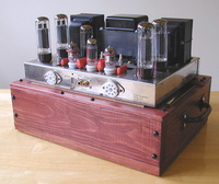
    Enjoy your ST-70 in whatever format you use, it's a great sounding amp.

    danielrhall likes this post

    boscode
    boscode


    Posts : 5
    Join date : 2015-06-11

    Setting the gain on an ST-70 Empty Re: Setting the gain on an ST-70

    Post by boscode Thu Jan 21, 2021 4:52 pm

    Has anyone tried decreasing feedback in the ST-70 by just replacing the 1k feedback resistors with 2.2k (or any other value) keeping them on the 16 ohm tap and everything else the same?
    Thanks.
    avatar
    dcboucher


    Posts : 6
    Join date : 2021-01-11

    Setting the gain on an ST-70 Empty Re: Setting the gain on an ST-70

    Post by dcboucher Thu Jan 21, 2021 7:50 pm

    I use the 16 ohm tap and I'm intrigued by boscode's idea. I have a pair of mic pre's with variable feedback to get more color or clarity to the sound. Could you put pots in place of those feedback resistors to be able to dial in your system?

    Solder Slinger, you are definitely way ahead of me. I really like the varistor idea for the power tranny. It looks like a past owner has replaced the biasing resistors and they measure well matched, albeit a shade high. How much power would that 1 ohm resistor need to be able to withstand? 1/2W at the most, if my math is correct. Even a 1/4W would probably work.

    I'm in full tilt mixing panic at the moment, so tinkering is off the table for now. I even feel a bit guilty about the 10 minute break i just took to look at my amp and read and understand your reply, but who can resist when you get that email about someone chiming in on your post? Not me.

    Thanks everyone!

    -d
    avatar
    Solder Slinger


    Posts : 36
    Join date : 2009-05-24

    Setting the gain on an ST-70 Empty Re: Setting the gain on an ST-70

    Post by Solder Slinger Thu Jan 21, 2021 9:31 pm

    Hi dcboucher'

    I usually use 1/2 watter to measure the bias, although if I remember correctly, one of the "old timers" at DIYTube.com (which is gone now, unfortunately) indicated a 1/4 watt with the comment that if the tube red-plated, the 1/4 would burn out and keep other damage from happening.

    Regarding the CL-80 or a pair of CL-90s in parallel, I usually put them on the hot (black) lead. They definitely stop the slam on power hit the transformer and the tube heaters get.

    Concerning feedback: try a 2.2k and a 4.7k in place of the 1K, see if you like the results. If you want to experiment, lift the wires at eyelets 12 and 13, solder in a 1k to the eyelet (to get 2k total or a 2.2 to get 3.2 k total then tack the wire you lifted to the other end of the resistor. Not a permanent job but ok to experiment with different feedback values WITHOUT taking a chance on damaging the old printed circuit board... (ask me how I came to that conclusion...)

    Also try lifting the wire at eyelets 11 and 14 to eliminate the 390 pf cap from the feedback circuit and just use resistors in the feedback circuit.

    Or lift 11, 12, 13 and 14 to try the amp with no feedback (be sure to insulate the disconnected wire ends).

    YMMV

    Just some thoughts.

    -Ed

    danielrhall likes this post


    Sponsored content


    Setting the gain on an ST-70 Empty Re: Setting the gain on an ST-70

    Post by Sponsored content


      Current date/time is Thu May 02, 2024 8:07 pm