The Dynaco Tube Audio Forum

Would you like to react to this message? Create an account in a few clicks or log in to continue.
The Dynaco Tube Audio Forum

Dedicated to the restoration and preservation of all original Dynaco tube audio equipment - Customer support for Tubes4hifi VTA tube amp and preamp kits and all Dynakitparts.com products


5 posters

    Low Rectifier Voltage output after SDS Cap board install.

    avatar
    MikeyV


    Posts : 16
    Join date : 2010-09-05

    Low Rectifier Voltage output after SDS Cap board install. Empty Low Rectifier Voltage output after SDS Cap board install.

    Post by MikeyV Sun Sep 05, 2010 11:22 pm

    Hello Everyone,
    I just recently installed the SDS Capacitor replacement board on my two Dynaco MKIIIs.
    These amps were bone stock, factory assembled units.

    After installing the SDS boards, I fired them up, and attempted to bias.
    What I found was that I could not get the bias voltage (measured at the stock test point) down to 1.56, about 2.4 is the lowest I could get it.

    So I started checking voltages. What I found is that I'm only getting 372 volts DC at pin 8 of the Rectifier tube. The PT is putting 425 Volts AC onto pins 4/6 of the rectifier. Even if I disconnect the wire going from pin 8 of the Recto to the SDS cap board, I still only get about 390 VDC.

    Bad rectifier, you say? I have 4 GZ34 rectos and all give me the same reading.

    I must be missing something simple, because, like a moron, I did the mod to TWO amps at the same time, not firing one up and leaving the other for reference. Both amps behave exactly the same, so I 'm thinking I missed something simple...

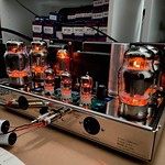
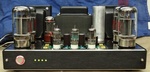
    Before me messing with them, they both worked fine, biased to 1.56 V, The Recto was out-putting around 500 Volts(seeing that is what scared me into replaceing the Cap can.) Everything was cool. Let me see if I can upload some pics of the boards inatalled into the chassis.

    Thanks for any help.
    Mike
    Bob Latino
    Bob Latino
    Admin


    Posts : 3263
    Join date : 2008-11-26
    Location : Massachusetts

    Low Rectifier Voltage output after SDS Cap board install. Empty Re: Low Rectifier Voltage output after SDS Cap board install.

    Post by Bob Latino Mon Sep 06, 2010 6:35 pm

    Hi Mike,

    The thing that really seems near impossible (from your description) is that with the line from pin 8 of the rectifier to your SDS board DISCONNECTED you only get 390 VDC off pin 8 with 425 VAC on pin 4 and 6 to chassis ground. And you said that you tried it with FOUR rectifier tubes and got the same reading? That is strange.

    Check the 5 volt AC line that feeds the rectifier tube. ( the two white wires on pins 2 and 8 ) See if you get the full 5 volts AC across these two filament wires that drive the heater on the rectifier tube with the amp on and the rectifier in there. Maybe the voltage is low ? A low voltage here could cause the symptoms you describe with not enough heater current to drive the rectifier tube. If that is the case, you probably need a new power transformer.

    Let us know what you find ?

    Bob
    avatar
    MikeyV


    Posts : 16
    Join date : 2010-09-05

    Low Rectifier Voltage output after SDS Cap board install. Empty Re: Low Rectifier Voltage output after SDS Cap board install.

    Post by MikeyV Fri Sep 10, 2010 2:35 pm

    thanks for the reply Bob, sorry to not get back sooner, I was testing some things out to make sure I'm not missing something.

    Yeah, I know, that sounds impossible.

    I get the full 5.3VAC on the rectifier heaters.

    this last week, I was testing these rectifier tubes out, usinf a guitar amp that uses the GZ34 Rectifier. That amp (fender deluxe clone from Weber) puts out 282VAC (measured from pin to chassis) off the Power Transformer. I tried all four rectifiers, and also a Weber Coper Cap rectifier, and they all worked, putting between 355 and 385 volts CD out onto pin 8 of the rectifier.

    I checked and recorded all the voltages:
    PT:
    Red leads = 425VAC measured from pin to chassis.
    Yellow = 5.6 VAC measure across pins
    Green = 6.5 VAC measured across the pins
    Red Black Bias = 56 VAC and near 80 VDC after teh Selenium Rectifier.

    This is really making me scratch my head.
    I'm going to check it out some more tonight.

    One thing that seems weird to me, and may provide a clue:

    On the dynacos, I get no reading if I measure across pins 4/6 on the rectifier tube. If I measure from one pin to the chassis, I get the 425 VAC that's expected. On yellow and green heaters, If I measure from pin to pin, I get the full 5.4 or 6.5 VAC, ie the full swing. If I measure pin to ground, I get half voltage, 2.6 or 3.2 VAC.

    Now, I think this is mostly normal, but is it weird that I can't read a voltage across pins 4/6, but only from one pin to ground?

    Reason I ask this is because on the Fender amp I was comparing, If I measure the PT output pin to pin, I get 565 VAC, the full swing, but if I measure pin 4 or pin 6 to ground, I get half swing, or 282 volts.

    THANKS!!! I know this must be something we can figure out.
    Bob Latino
    Bob Latino
    Admin


    Posts : 3263
    Join date : 2008-11-26
    Location : Massachusetts

    Low Rectifier Voltage output after SDS Cap board install. Empty Re: Low Rectifier Voltage output after SDS Cap board install.

    Post by Bob Latino Fri Sep 10, 2010 2:52 pm

    Mike,

    If you get 425 VAC from both pins 4 and 6 to chassis ground on the rectifier tube you should get double the voltage or 850 VAC across pins 4 and 6. This should be just as you mentioned on the Fender amp - double the voltage across the two pins.

    Can you check your meter against another meter ? Something is not right there ?

    Bob
    avatar
    MikeyV


    Posts : 16
    Join date : 2010-09-05

    Low Rectifier Voltage output after SDS Cap board install. Empty Re: Low Rectifier Voltage output after SDS Cap board install.

    Post by MikeyV Fri Sep 10, 2010 3:35 pm

    Hi Bob, I'm home for lunch and I checked it out.

    My meter says right on the front, 650V max. I never noticed, I'm bad apparently.
    The meter looks like it's maxing out or malfunctioning when trying to read that large voltage.
    It dosen't read "0.00" or anything like that. I'd take some hunting to check the meter against another, or procure another. Maybe I should just buy a fluke...

    I know that the PTs worked right before my SDS board install. They biased properly, I had 500 plus volts on pin 8 of the rectifier. It sgotta be something I did, cause both amps are doing the same thing.

    I'm going to desolder the lead of pin 8 on both amps and check this stuff again.
    Perhaps my meter is crapping out at 525 V that the recto is putting out and giving me a bad reading.

    But, if my meter is innacurate at large voltages, is must be better down low, like with the heaters and the bias voltages, and anything under 400 or so, it reads like I'd expect.

    Which makes the fact that I can't get the bias voltage below 2.4V at the test point even weirder.

    Obviously, I need to check these high voltages (825V from the PT and 525 Volts on pin 8 ) with a good meter. Gimme some time and I'll do that and get back.
    Thanks for the help, please post if you have any thoughts.

    Can I send you a few pics to check out? I tried posting them, but coundn't.
    Thanks

    Mike

    Bob Latino
    Bob Latino
    Admin


    Posts : 3263
    Join date : 2008-11-26
    Location : Massachusetts

    Low Rectifier Voltage output after SDS Cap board install. Empty Re: Low Rectifier Voltage output after SDS Cap board install.

    Post by Bob Latino Fri Sep 10, 2010 3:45 pm

    Hi Mike,

    Yes - get another meter and check it against the one you have. If you buy another meter - yes - a Fluke is probably the best. I have a Fluke Model 115 that works well. It also measures capacitance if you want to check whether a cap is bad or not. The 115 is about $125.

    To post a photo on this Forum you have to host the photo on another web site and then link to the photo. This forum is supposed to be able to host a photo but it just doesn't work.

    Bob
    avatar
    MikeyV


    Posts : 16
    Join date : 2010-09-05

    Low Rectifier Voltage output after SDS Cap board install. Empty Re: Low Rectifier Voltage output after SDS Cap board install.

    Post by MikeyV Mon Sep 13, 2010 4:20 pm

    Hi Bob,
    OK, I procured a Fluke 175 this weekend.

    The readings with the Fluke are all the same as with the Radio Skack DDM, with the exception that I can now read the AC vlotage on the primarys of the PT, it reads 850VAC.

    As before, EAch individual primary reads about 425 VAC (terminal to chassis), the heaters on the rectofier socket give 5.3 VAC terminal to terminal.

    Today, at lunch, I unsoldered the lead off of therectifier tube (to be clear, there are 4 wires now hooked up to the rectifier tube, 2 red primaries, and 2 yellow heaters, all from the PT)

    I get 412 VCD on pin 8 of the rectifier. I tried two rectifiers, and got the same voltage.

    On the other amp, I get 390 VAC from Primary to chassis, about 775 VAC across the primaries, and about 395 VCD on pin 8 of the rectifier, again, without the rectifier connected to the rest of the circuit.

    This makes no sense. You probably think I'm crazy. I'm going to work on posting some pics on Photobucket or something.

    I'm also going to buy a new rectifier to test.

    Thanks for the help
    Mike
    Bob Latino
    Bob Latino
    Admin


    Posts : 3263
    Join date : 2008-11-26
    Location : Massachusetts

    Low Rectifier Voltage output after SDS Cap board install. Empty Re: Low Rectifier Voltage output after SDS Cap board install.

    Post by Bob Latino Mon Sep 13, 2010 7:01 pm

    Hi Mike,

    Yes - post a photo of the internal wiring of the amp. Maybe by looking at the wiring one of us can pick up on something ...

    Bob
    avatar
    MikeyV


    Posts : 16
    Join date : 2010-09-05

    Low Rectifier Voltage output after SDS Cap board install. Empty Re: Low Rectifier Voltage output after SDS Cap board install.

    Post by MikeyV Wed Sep 15, 2010 6:17 pm

    Here are a few pics. they show:

    the Amp before I touched it (factory wired)
    The amp with the SDS board mounted, but no wired moved
    The amp with the SDS board installed and connected
    The old Cap Can as it stands now, unhooked.

    All I did was move the leads off of the Cap Can, and sent then to the SDS board,
    Namely, I moved 2 choke wires, 1 Rectifier output wire, 1 red PT center tap wire, the wire from point 5, and the wire from point 6 on the circuit board. That's it.

    Here are some pics: https://s1237.photobucket.com/albums/ff479/Mikeyv1231/
    avatar
    stewdan


    Posts : 231
    Join date : 2010-03-07
    Age : 85
    Location : Houston Texas

    Low Rectifier Voltage output after SDS Cap board install. Empty Re: Low Rectifier Voltage output after SDS Cap board install.

    Post by stewdan Sun Feb 27, 2011 2:34 pm

    Mike --

    I realize that this is an old thread, but did you ever solve the problem?

    I ask because I think I have a similar problem with a "sort-of-stock" Mark 3 and a SDS Cap Board that I just put into an old Mark 3 that I recently acquired.

    By "sort-of-stock" I mean the driver board was replaced by me with a modern version of the old board and the Quad Cap and its extra dangling electrolytic caps were replaced by an SDS Cap Board (also by me). Oh, I also replaced the selenium rectifier and the bias caps with a 1N4005 diode and 2 new 100MF/160v electrolytic caps.

    I have done all of this before on other Mark 3s and not seen any problems. Maybe I was lucky??

    If you solved your problem please let us know!!

    Stew
    avatar
    MikeyV


    Posts : 16
    Join date : 2010-09-05

    Low Rectifier Voltage output after SDS Cap board install. Empty Re: Low Rectifier Voltage output after SDS Cap board install.

    Post by MikeyV Mon Feb 28, 2011 7:58 pm

    NICE!! It's good to see this come up.

    No, I haven't fixed them yet, they're just sitting, collcting dust, and I'm listening to my back-up Onkyo, sounds terrible. Sad
    So are you saying you have the same problem? Where you cant get full rectified voltage out of the rectifier? I'd love to begin talking about this again, because I dont know how much more Onkyo I can take. Neutral
    avatar
    stewdan


    Posts : 231
    Join date : 2010-03-07
    Age : 85
    Location : Houston Texas

    Low Rectifier Voltage output after SDS Cap board install. Empty Low Rectifier Voltage

    Post by stewdan Mon Feb 28, 2011 11:14 pm

    Hi Mike -

    Yes, I definitely have some sort of a rectifier voltage problem on the Mark III. On pins 4 and 6(red Wires), I am seeing the nominal 425v to ground, but on on Pins 2 and 8 by (Yellow Wires) themselves I am getting almost no reading at all. Sometimes the tube heaters are functional and sometime the tubes are dark.

    On Friday, I had tubes glowing plus low voltages on 2 and 8 and also had very low sound coming out of the speaker I had hooked up.

    Monday morning I had the same conditions, but in the afternoon I had dark tubes, no voltage on 2 and 8 and no sound. I am starting to think I may have a power transformer problem also, since the Tranny wires are real faded and brittle??

    If it wasn't for Bob's Colored Wire Pictorial of the Mark III, I would have a very hard time telling what wire is what color.

    Oh well, tomorrow I will change out the 45+ year old power switch and start working myself downstream and see what happens.

    Stew
    Shocked
    avatar
    stewdan


    Posts : 231
    Join date : 2010-03-07
    Age : 85
    Location : Houston Texas

    Low Rectifier Voltage output after SDS Cap board install. Empty Re: Low Rectifier Voltage output after SDS Cap board install.

    Post by stewdan Sat Mar 05, 2011 3:40 pm

    Mike --

    Just to let you know, I changed out the power switch and now have glowing tubes and the very low sound from the speaker. The glowing tube condition seems to be permanent, unlike the case with the old switch.

    That is all I had time to do. I will try to get back to it next week.

    Stew
    Bob Latino
    Bob Latino
    Admin


    Posts : 3263
    Join date : 2008-11-26
    Location : Massachusetts

    Low Rectifier Voltage output after SDS Cap board install. Empty Re: Low Rectifier Voltage output after SDS Cap board install.

    Post by Bob Latino Sat Mar 05, 2011 6:48 pm

    Stew,

    Try checking the AC voltage ACROSS pins 2 and 8 of the rectifier socket. You should get about 5 volts AC where those two white wires connect to the rectifier socket. If you don't the power transformer could be bad.

    If you get the proper voltages then do a full voltage check on your ST-70 - voltage reading below for a stock ST-70

    Bob
    Voltage readings - Stock ST-70
    * Note # 1 – Make sure you have your meter set to AC or DC as mentioned below. Ground is any point on the chassis frame. Place the black or negative probe on the chassis and the red or positive probe on the point mentioned. All tubes should be plugged in, inputs shorted or connected to your preamp, speakers connected and no signal should be running through the amplifier. Be careful not to cross two pins with the positive probe !

    * Note # 2 – Readings very slightly above or very slightly below the range are not normally a sign of a problem. Line voltages vary slightly throughout the country. Differences in the GZ34 rectifier tube can cause variations also.

    GZ34 – Pin 2 to ground – 460 - 480 volts DC
    Pin 8 to ground – 460 - 480 volts DC
    Pin 4 to ground – 380 - 400 volts AC
    Pin 6 to ground – 380 - 400 volts AC
    ACROSS pins 2 and 8 >> 5 volts AC

    Any EL34 – Pin 1 to ground – approx 1.56 volts DC (depends on bias setting)
    Across pins 2 and 7 – 6.2 – 6.8 volts AC
    Pin 3 to ground – 430 - 460 volts DC
    Pin 4 to ground – 430 - 460 volts DC
    Pin 5 to ground – minus 25 to minus 40 volts DC
    Pin 6 to ground – minus 25 to minus 40 volts DC
    Pin 8 to ground – approx 1.56 volts DC (depends on bias setting)

    Quad cap – Section # 2 (half circle symbol) --- 435 – 450 volts DC (faces rectifier)
    Section # 1 (NO symbol) ------------ 425 – 440 volts DC (faces back of amp)
    Section # 4 (triangle symbol) ----- 390 – 420 volts DC
    Section # 3 (square symbol) ------ 290 - 330 volts DC (faces front of amp)
    avatar
    MikeyV


    Posts : 16
    Join date : 2010-09-05

    Low Rectifier Voltage output after SDS Cap board install. Empty Re: Low Rectifier Voltage output after SDS Cap board install.

    Post by MikeyV Tue Jan 30, 2018 5:14 pm

    Guys, here it is, 2018, and my MKIIIs still don't work.

    I did accomplish moving, marriage, procreation (twice) and working.  Anyone with kids knows how hobby time is pretty scarce.  Even worse when you have multiple hobbies.

    I'm going to really try to get these going.
    To recap, I have two factory wired MKIIIs, a few serial numbers apart.  They were bone stock when I received them.

    I used them for a few months, sounds nice. Then they did a bit of sparking in the GZ34 and in the KT88s.  The tubes were probably original, so like early 1960's original (RCA KT88s, Sylvania GZ34s).  The tubes lost their getter, and were obviously shot.

    I bought new JJ KT88s and GZ34s. Installed them,  biased them, and they played, but then started sparking. I then bought and installed SDS cap boards.  The amps have their original bias circuit, which seems to work (see below)  but I do have kits to replace them handy.

    Maybe we can walk this down from the PT?

    Wall voltage: 121.5 VAC across wires
    Red Wires:829 VAC across the wires, 415 VAC from each wire to chassis
    Yellow Wires: 5.45 VAC across the wires to rectifier
    Red/Yelow: 0                              
    Red/Black: 58 VAC wire to Chassis
    Green/Yellow: 0 grounded    IS THIS A PROBLEM?  Should it be 3.15 VAC?
    Green:  6.95 VAC across the wires

    Output lug of Selenium Rectifier is -75 VDC to chassis.

    Bias voltage at pin 5 of output tubes holds steady at -55 VDC, Bias pot has good range.


    If I put in a Rectifier (I have two JJ GZ34s, and a Weber Copper Cap Rectifier)
    All give this reading: 392 VDC on the RED wire to the SDS board.

    Voltage at circuit board Pin 4: 392 VDC
    Voltage at circuit board Pin 5: 367 VDC
    Voltage at circuit board Pin 6: 332 VDC

    I tried one of the original Sylvania 5AR4/GZ34 and get the same numbers.
    A second JJ GZ34 gives the same numbers also.
    I have a Weber coper cap rectifier, but I can't get in in the socket. It's got all it's pins, and I think the empty pin holes in the socket have never been used, so it's reluctant to go in.

    The amp will sit like this (Rectifier in, no tubes, no hook-ups, pre-amp tube in) with stable voltages.

    So far so good?  I did the same with the second amp, no different, except the PT red wires are 435 VAC wire to chassis.  The rectifier in this one makes 412 VDC.
    For second amp:
    Voltage at circuit board Pin 4: 412 VDC
    Voltage at circuit board Pin 5: 385 VDC
    Voltage at circuit board Pin 6: 348 VDC

    What should the GZ34 be putting out with these input voltages (415 - 435 VAC to chassis)?

    Thanks for the help, I'm glad to be back, and glad you guys are around!

    Cheers,
    Mike

    PS, Gonna try to put some power tubes in.
    corndog71
    corndog71


    Posts : 840
    Join date : 2013-03-19
    Location : It can get windy here

    Low Rectifier Voltage output after SDS Cap board install. Empty Re: Low Rectifier Voltage output after SDS Cap board install.

    Post by corndog71 Tue Jan 30, 2018 6:54 pm

    Maybe replace that rectifier socket. Speaking of rectifiers, maybe replace the diode in the bias circuit too. Then again, if I were you I would put those in storage as collector's items and build brand new amps with modern circuits for regular listening.
    avatar
    MikeyV


    Posts : 16
    Join date : 2010-09-05

    Low Rectifier Voltage output after SDS Cap board install. Empty Re: Low Rectifier Voltage output after SDS Cap board install.

    Post by MikeyV Wed Jan 31, 2018 3:31 pm

    So I tried the Weber Copper Cap in the MKiii.  435 VAC in from the PT, 415 VDC out of the rectifier.
    This is the same as the three GZ34s I have.

    I tried the GZ34 in another guitar amp I have apart, the PT provided 290 VAC into the rectifier, and 404 VDC out.

    So what is wrong with my PT?  Why would 435 VAC in make only 415 out of a rectifier that's proven to be good?  It should be 490-500, right? Does this mean the PT is failing?  Both my MKiiis act the same.

    If I hook up to a speaker, and short the input jack (to leave open, makes no diff)  All I get is LOUD hum out of the speaker.

    I do get -55 VDC at pin 5 of the power tubes, but I get a voltage reading of 0.000 VDC at the boat test point.  The resister measures 11.3 Ohms, so that's good.

    Help!  

    Thanks
    Mike
    avatar
    MikeyV


    Posts : 16
    Join date : 2010-09-05

    Low Rectifier Voltage output after SDS Cap board install. Empty Re: Low Rectifier Voltage output after SDS Cap board install.

    Post by MikeyV Wed Jan 31, 2018 9:06 pm

    OK, I unsoldered the lead from the rectifier to the SDS board. Power tubes out, rectifier in, no input, no speaker connections.

    There are only 4 wires connected to the rectifier socket, the yellow heaters, which read 5.3 VAC across, and the red primaries which measure 435 VAC to the chassis.

    Output of rectifier is 425 VDC.

    Seems impossible. The tube worked properly in another amp, like I said above.

    Does this mean my power tranny is bad?

    pichacker
    pichacker


    Posts : 103
    Join date : 2016-08-01
    Age : 59
    Location : Near to London - UK

    Low Rectifier Voltage output after SDS Cap board install. Empty Re: Low Rectifier Voltage output after SDS Cap board install.

    Post by pichacker Fri Feb 02, 2018 5:20 am

    So you mention a loud hum with the IP shorted. For you to have such a low DC voltage without anything smoking I am thinking that maybe you haven't got a ground on the reservoir caps? Looking at the SDS site the ground appears to be provided by the mounting screw to the PCB. Check that the -ve side of the lower caps (2,4,6,8 ) are actually connected to ground via the PCB. (Star ground point?)

    If you still have the Fluke mentioned earlier switch it to AC and measure the DC rail. It should read a minimal ripple voltage. If you have a significant reading of many volts there's your answer.

    Another way of checking this theory is if your old quad cap is still in place, is to connect a link between the rectifier valve cathode and the first section like it used to be. If the voltage rises back to the normal level then the new caps are not properly in circuit.
    avatar
    MikeyV


    Posts : 16
    Join date : 2010-09-05

    Low Rectifier Voltage output after SDS Cap board install. Empty Re: Low Rectifier Voltage output after SDS Cap board install.

    Post by MikeyV Fri Feb 02, 2018 1:13 pm

    Houston, we have a problem.

    Thanks to Pichacker, I checked the grounding on the negative bus side of the SDS board.

    Guess, what, the metal ring in the mounting hole (that presumably is in contact with the ground bus on the board, so when you mount it to the chassis, it grounds it) is not, in fact, electrically connected to the ground bus.

    So I searched, and found this: https://dynacotubeaudio.forumotion.com/t1967-sds-labs-capacitor-board-hum-mark-iii

    Instruction sheet not updated.  Damn.  These amps have been down for 8 years...granted, I shelved them for a while, but still...

    So I will now look for an updated SDS sheet to see how to ground it.  I guess a wire attached to any negative hole, then a wire to chassis (under a bolt?)

    This must be the problem.  It would explain a lot.

    Thanks for the help, Pic...I'll report back.
    avatar
    MikeyV


    Posts : 16
    Join date : 2010-09-05

    Low Rectifier Voltage output after SDS Cap board install. Empty Re: Low Rectifier Voltage output after SDS Cap board install.

    Post by MikeyV Fri Feb 02, 2018 2:09 pm

    OK, placed a ground wire from the neg bus of the SDS to the ground lug of old Cap Can.

    Now, I get a LOT of Voltage:

    PT red wires = 435 VAC to chassis

    Rectifier out = 594 VDC!
    P4 on board = 592
    P5 on board = 544
    P6 on board = 450

    Bias still holding at -55 VDC.

    These voltages seem scary high. Like 100 volts over the ones in the manual.


    I've got 592 VDC on pins 3 and 4 of the KT88s. Without tubes installed. I'm a little scared to install tubes. I was getting sparking in the tubes before.

    Thanks for the help, I'm I think getting somewhere.
    pichacker
    pichacker


    Posts : 103
    Join date : 2016-08-01
    Age : 59
    Location : Near to London - UK

    Low Rectifier Voltage output after SDS Cap board install. Empty Re: Low Rectifier Voltage output after SDS Cap board install.

    Post by pichacker Fri Feb 02, 2018 2:13 pm

    Without the valves in the voltages will be higher than normal as no current is being drawn. So you now need to look into why the board didn't ground through the screw. You'll need to make a secure short in length local ground connection.

    Amazing what a fresh eyes approach can yield Smile
    avatar
    MikeyV


    Posts : 16
    Join date : 2010-09-05

    Low Rectifier Voltage output after SDS Cap board install. Empty Re: Low Rectifier Voltage output after SDS Cap board install.

    Post by MikeyV Fri Feb 02, 2018 2:15 pm

    The board didn't ground thru the screw because the screw hole is not electrically connected to the ground bus. Apparently, they forgot to put this in the instructions.

    I ran a wire from ground bus to the chassis. All good now. I'll put in some tubes, short the input, and hook up a speaker, then shield my face, and see what happens. I'll check the bias.

    Thanks man!
    avatar
    MikeyV


    Posts : 16
    Join date : 2010-09-05

    Low Rectifier Voltage output after SDS Cap board install. Empty Re: Low Rectifier Voltage output after SDS Cap board install.

    Post by MikeyV Fri Feb 02, 2018 2:32 pm

    It works!  525 VDC on the plates, bias set 1.56V at the test port.  Ran the amp for a few minutes on one channel from a Cell phone.  I'm gonna do the same to the other one.

    Filter caps weren't grounded.  Incredible.  Seems like a big thing to forget about in the SDS instructions.
    It's still not fixed in the available instructions.

    Pic, you da man.  My hero.  Thanks


    Last edited by MikeyV on Fri Feb 02, 2018 5:00 pm; edited 1 time in total (Reason for editing : read weird, and spelling)
    pichacker
    pichacker


    Posts : 103
    Join date : 2016-08-01
    Age : 59
    Location : Near to London - UK

    Low Rectifier Voltage output after SDS Cap board install. Empty Re: Low Rectifier Voltage output after SDS Cap board install.

    Post by pichacker Sun Feb 04, 2018 2:38 pm

    Glad I could help. Happy listening Smile

    Sponsored content


    Low Rectifier Voltage output after SDS Cap board install. Empty Re: Low Rectifier Voltage output after SDS Cap board install.

    Post by Sponsored content


      Current date/time is Sun Apr 28, 2024 10:10 am