The Dynaco Tube Audio Forum

Would you like to react to this message? Create an account in a few clicks or log in to continue.
The Dynaco Tube Audio Forum

Dedicated to the restoration and preservation of all original Dynaco tube audio equipment - Customer support for Tubes4hifi VTA tube amp and preamp kits and all Dynakitparts.com products


4 posters

    ST-70 rectifier diode mod novice question

    avatar
    raudio44


    Posts : 48
    Join date : 2014-09-12

    ST-70 rectifier diode mod novice question Empty ST-70 rectifier diode mod novice question

    Post by raudio44 Thu Jun 02, 2022 10:43 am

    Hi, a nice member made me aware of this mod and seemed like an easy one for a novice, non-tech as I am.

    Ok, a simple mod, right? of course when I went into my ST-70 to do it, there was NO slack in the power leads! figures.
    In an earlier post here, a member showed how he use a terminal strip, which was a good idea. now I do not have parts etc., and thought I'd give it a good try with what I had to work with.
    I have done only a couple things before, so it may not be perfect but doesn't seem too bad. Well, here is what I came up with and would appreciate some input on what I did and if it will be ok.
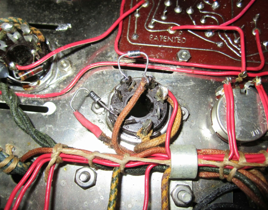
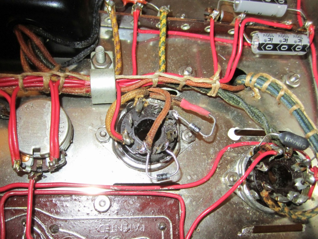
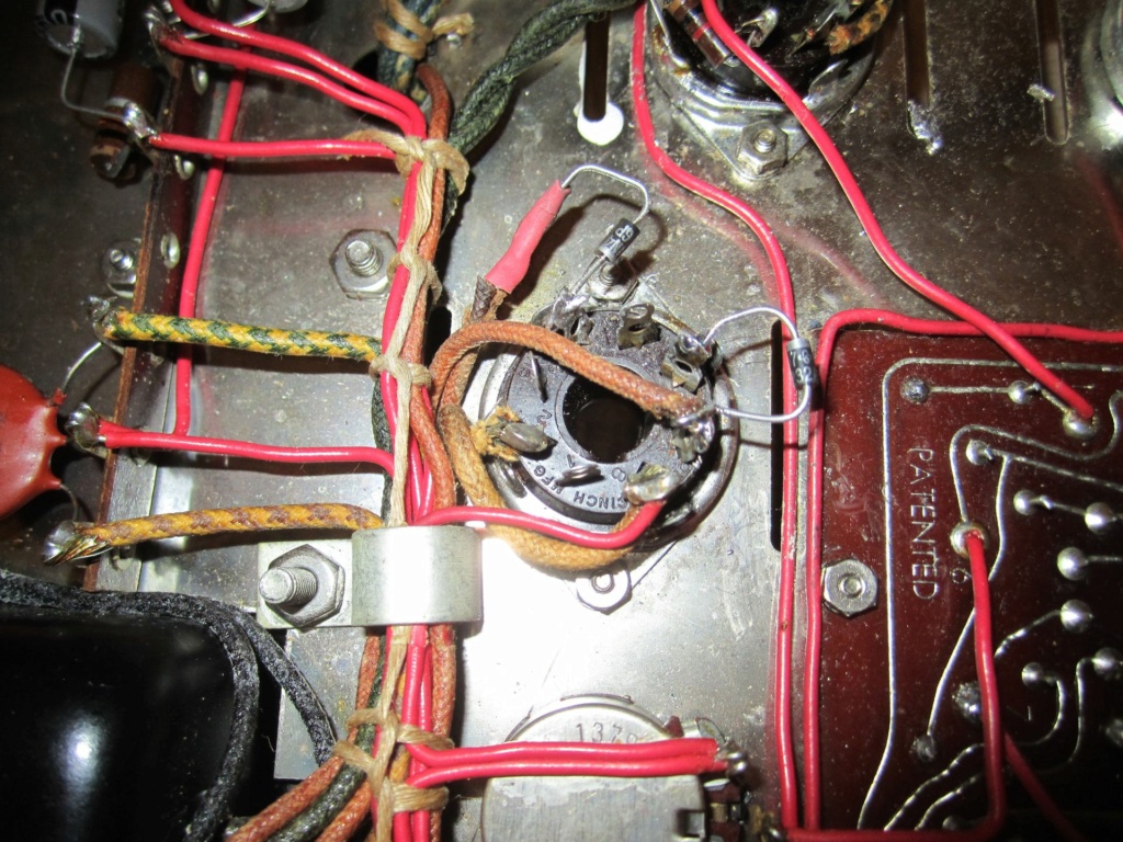
    Three of the four connections are solid, and on posts. Where I got 'creative' is the one not on a terminal. Made a direct connection with the power lead right to the diode and used a shrink tube to protect it and also, I thought it would add some 'mechanical' stability. So, am I ok? Thanks

    ST-70 rectifier diode mod novice question 1_st-710ST-70 rectifier diode mod novice question St-70_10ST-70 rectifier diode mod novice question 2_st-710

    peterh likes this post

    avatar
    Dale Stevens


    Posts : 201
    Join date : 2014-07-06
    Age : 75
    Location : Loris, SC

    ST-70 rectifier diode mod novice question Empty Re: ST-70 rectifier diode mod novice question

    Post by Dale Stevens Thu Jun 02, 2022 5:20 pm

    Yep, u're good. Just note that on your schematic for future. ( may be someone else) Nice job. Dale

    raudio44 likes this post

    avatar
    raudio44


    Posts : 48
    Join date : 2014-09-12

    ST-70 rectifier diode mod novice question Empty Re: ST-70 rectifier diode mod novice question

    Post by raudio44 Fri Jun 03, 2022 4:24 am

    Dale Stevens wrote:Yep, u're good. Just note that on your schematic for future. ( may be someone else) Nice job.  Dale


    Really appreciate your reply. Thought it was ok, but wanted to make sure the one connection was acceptable. Thank you, Rick
    Wotan
    Wotan


    Posts : 31
    Join date : 2018-02-11

    ST-70 rectifier diode mod novice question Empty Re: ST-70 rectifier diode mod novice question

    Post by Wotan Mon Jun 27, 2022 9:51 am

    The cathode lead looks a little close to shorting on the socket mounting screw for comfort, considering the other end is unsupported, but it's probably fine. Also, to be super-nitpicky, the shrink wrap should overlap the insulation of the wire. Should you consider a do-over? No, it'll be fine.

    In general, if a lead is too short, you can make a nice splice to an extra length of wire with solder and shrink wrap, just like you did with the diodes. You may even be able to find the same color wire and shrink wrap, so hardly anyone would notice.

    When doing a splice like that, an overlapping joint is fine, as you seem to have done with the diodes. You just need a way of keeping it aligned while the solder is cooling. A double wrap-around joint gives you far more physical strength than you need, and solves the problem of holding it in place, but carries a far greater risk of a sharp point poking through the shrink wrap. I speak from experience.
    avatar
    raudio44


    Posts : 48
    Join date : 2014-09-12

    ST-70 rectifier diode mod novice question Empty Re: ST-70 rectifier diode mod novice question

    Post by raudio44 Mon Jun 27, 2022 1:29 pm

    Wotan wrote:The cathode lead looks a little close to shorting on the socket mounting screw for comfort, considering the other end is unsupported, but it's probably fine.  Also, to be super-nitpicky, the shrink wrap should overlap the insulation of the wire.  Should you consider a do-over?  No, it'll be fine.

    In general, if a lead is too short, you can make a nice splice to an extra length of wire with solder and shrink wrap, just like you did with the diodes.  You may even be able to find the same color wire and shrink wrap, so hardly anyone would notice.

    When doing a splice like that, an overlapping joint is fine, as you seem to have done with the diodes.  You just need a way of keeping it aligned while the solder is cooling.  A double wrap-around joint gives you far more physical strength than you need, and solves the problem of holding it in place, but carries a far greater risk of a sharp point poking through the shrink wrap.  I speak from experience.

    Hi, really appreciate your observations. This was my first time doing this, did what I could. That lead is not as close to the mounting screw as it seems in the picture and, FWIW, the diode is really sitting pretty firm suspended as it is. Yeah, my initial thought regarding the other diode was to splice in some wire instead of having the cable pulled across the bottom of the socket. Well, I didn't have any wire, but with a little coaxing, I got the original wire to fit with a solid connection. Not a tech so do not have parts etc. around. oh well. 

    Understand about the shrink wrap not over the insulation, saw that after I did it, but it seemed close enough (said the novice). was hoping it was ok.

    Also understand what you mean about sharp edges piercing the wrap.

    While I was in there, I managed to upgrade the speaker binding posts which I forgot to have done years ago when I had someone (referred by Bob Latino) update the amp. I knew nothing about it at the time and wanted it checked out. I know more now at least. My rationale was, paying to have it checked out was offset by the fact that the amp was given to me from a friend. Well early 70s with med issues and now major back problems but tying anyway. Thank you again,  R
    avatar
    speedyk


    Posts : 9
    Join date : 2015-03-28

    ST-70 rectifier diode mod novice question Empty Re: ST-70 rectifier diode mod novice question

    Post by speedyk Mon Jun 27, 2022 2:04 pm

    One could twist a rubber bumper on the end of the mounting bolt, which could also support the diode lead in case of a dropped component or other impact.

    If you ever want to put shrink on something already assembled, slice the smallest diameter that will fit lengthwise and slip over, then slice one a size up and slip it over so the slice is on the opposite side. Another layer above those won't hurt. Then heat the whole mess to shrink. That won't be as secure as doing it Hoyle, but will be better than nothing and further heating won't hurt it.

    I agree that it looks good as-is.

    raudio44 likes this post

    avatar
    raudio44


    Posts : 48
    Join date : 2014-09-12

    ST-70 rectifier diode mod novice question Empty Re: ST-70 rectifier diode mod novice question

    Post by raudio44 Tue Jun 28, 2022 2:32 am

    speedyk wrote:One could twist a rubber bumper on the end of the mounting bolt, which could also support the diode lead in case of a dropped component or other impact.

    If you ever want to put shrink on something already assembled, slice the smallest diameter that will fit lengthwise and slip over, then slice one a size up and slip it over so the slice is on the opposite side. Another layer above those won't hurt. Then heat the whole mess to shrink. That won't be as secure as doing it Hoyle, but will be better than nothing and further heating won't hurt it.

    I agree that it looks good as-is.
    Good thought about the rubber bumper. I actually started to put another wrap on but wanted to finish something else first and then just left it.
    You got me thinking now (hey, a good thing) so while I still have it on the table (don't have a proper workbench), I may open it up and take another look. I could just see if just bending the diode away from being over that socket screw to be extra sure. as it is, it is pretty solid. 

    Just did a good clean and polish of the chassis. cleaned the tube pins. not sure what to do, if anything about the sockets. thinking just inserting the tubes in and out a couple times.
    good tip on using the wraps.

    Really appreciate your thought and ideas, thank you

    Sponsored content


    ST-70 rectifier diode mod novice question Empty Re: ST-70 rectifier diode mod novice question

    Post by Sponsored content


      Current date/time is Sat Apr 27, 2024 5:31 pm