The Dynaco Tube Audio Forum

Would you like to react to this message? Create an account in a few clicks or log in to continue.
The Dynaco Tube Audio Forum

Dedicated to the restoration and preservation of all original Dynaco tube audio equipment - Customer support for Tubes4hifi VTA tube amp and preamp kits and all Dynakitparts.com products


4 posters

    M125 transformer and board cutout dimensions

    avatar
    Rec


    Posts : 71
    Join date : 2020-03-11

    M125 transformer and board cutout dimensions Empty M125 transformer and board cutout dimensions

    Post by Rec Sun Dec 11, 2022 12:27 pm

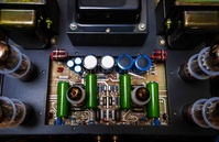
    Im in the process of designing a new plate for my m125s. Planning on Autobias, and solid state rectification under the hood, along with a stiffer B+ supply.

    I like to use CAD and laser cutting, as such I need to have some reliable dimensions for the power transformer, output transformer and driver board cutouts.

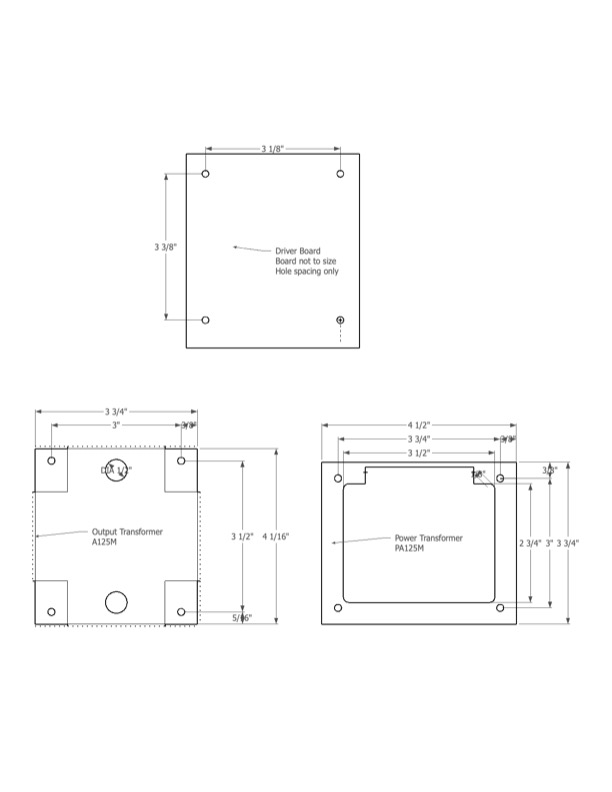
    I came up with attached using a micrometer, but Im hoping one of the tubes4hifi folks have this info readily? Or maybe someone has been down this road before?

    Thanks so much. Here is a dimensioned drawing of what I came up with, hoping for verification? Happy to post the final layout in case anyone wants.

    Appreciate it.

    M125 transformer and board cutout dimensions Dimens11
    Roy Mottram
    Roy Mottram
    Admin


    Posts : 1839
    Join date : 2008-11-30

    M125 transformer and board cutout dimensions Empty Re: M125 transformer and board cutout dimensions

    Post by Roy Mottram Sun Dec 11, 2022 2:20 pm

    those dimensions are all correct

    Rec likes this post

    avatar
    Rec


    Posts : 71
    Join date : 2020-03-11

    M125 transformer and board cutout dimensions Empty Re: M125 transformer and board cutout dimensions

    Post by Rec Sun Dec 11, 2022 4:36 pm

    Thank you!!
    Seamus
    Seamus


    Posts : 79
    Join date : 2020-03-17

    M125 transformer and board cutout dimensions Empty Re: M125 transformer and board cutout dimensions

    Post by Seamus Mon Dec 12, 2022 12:45 pm

    There's a beautiful build here Ken Galer's M-125

    Be careful as Ken found out, changing the layout and C can cause stability problems.

    There are innumerable tales of woe online wherein changing C in a tube amplifier creates an oscillator rather than an improved amplifier.

    These instructions for building an UltraLinear only version M-125 UltraLinear cover bigger C, increased stability, SNR improvements.
    avatar
    Rec


    Posts : 71
    Join date : 2020-03-11

    M125 transformer and board cutout dimensions Empty Re: M125 transformer and board cutout dimensions

    Post by Rec Mon Dec 12, 2022 1:53 pm

    Thanks!

    I have looked at those/that site, also saw Ken Galler's build. Read through the suggested changes. Have you made any of them?

    Ive seen a few posts where snubbers were added (resistor/inductor) between plate/g2 and the opt. to fix oscillations. Wasn't clear to me these were related to layout or increased C? That said, it is a beautiful build.

    My 125s are basically great, I listen to them daily on BW 702S2. They are stock, but in an effort to eliminate a slight 'buzz' in one amp I have made/accumulated the following tweaks:

    Nylon Screws
    10Ohm resistor grounds to star
    Mogami shielded input, with a small cap to chassis at input
    layout double/triple/check

    Octets of matched tubes are expensive. Redplating sucks. Matching replacements can be a challenge.
    Tough on rectifiers. I now just use my DIY Weber WZ68s. CL90 for delay.
    I still need to run them with the grounds lifted, otherwise I get a slight ear to cone buzz on one amp, this annoys me. This could be tubes. Is it oscillations!? I give up.

    So who knows where this will take me. That's the beauty of this kind of product.

    Seamus
    Seamus


    Posts : 79
    Join date : 2020-03-17

    M125 transformer and board cutout dimensions Empty Re: M125 transformer and board cutout dimensions

    Post by Seamus Wed Dec 14, 2022 5:57 pm

    When assembling a system, always start with the power amps only with shorted inputs. If the system is silent, then any noise added with upstream components is where the problem lies and needs fixing before proceeding.

    If you plug in each amp individually with a grounded cord and a shorting plug in the input, does either amp buzz?

    Does the noise remain with the amp if you change speakers? [Very unlikely to be speaker caused, but never say never]

    Is the noise 60Hz, 120Hz or something else?

    Do the quiet amp power tubes buzz in the other amp? [Label tubes so they can always be returned to the original site]


    avatar
    Rec


    Posts : 71
    Join date : 2020-03-11

    M125 transformer and board cutout dimensions Empty Re: M125 transformer and board cutout dimensions

    Post by Rec Wed Dec 14, 2022 6:49 pm

    Thanks.

    Each amp shorted. 3 wire. Both on. Quiet

    Source on “mute”, 3 wire. Both on, “buzz”, typically right amp buzz vs 60/120 hum. One on, either, quiet. Lifted both quiet. I tried a loop breaker in chassis, this worked, but really no room in the chassis unless I hack around.

    I’ve stopped chasing and just listen “lifted”. Keep you posted on my “update”. Still in planning phase.

    Another tube amp subbed into chain, dead silent. I built this one too.

    I think the amps either interact or maybe I have the dreaded ossification already….
    Seamus
    Seamus


    Posts : 79
    Join date : 2020-03-17

    M125 transformer and board cutout dimensions Empty Re: M125 transformer and board cutout dimensions

    Post by Seamus Thu Dec 15, 2022 12:14 pm

    You could try reversing the line voltage wiring in the buzzy amp.
    avatar
    Rec


    Posts : 71
    Join date : 2020-03-11

    M125 transformer and board cutout dimensions Empty Re: M125 transformer and board cutout dimensions

    Post by Rec Fri Dec 16, 2022 12:28 pm

    Hey why not worth a shot!
    MechEngVic
    MechEngVic


    Posts : 106
    Join date : 2019-01-16

    M125 transformer and board cutout dimensions Empty Re: M125 transformer and board cutout dimensions

    Post by MechEngVic Sun Jan 01, 2023 3:09 am

    A method I use to chase down buzz is to tie a wire to the chassis of one component then use that wire to probe ground points of other components. Chassis, input cable grounds, voltage input grounds, transformer bodies, etc. Then switch tie down point and re-probe.

    Sponsored content


    M125 transformer and board cutout dimensions Empty Re: M125 transformer and board cutout dimensions

    Post by Sponsored content


      Current date/time is Wed May 01, 2024 11:45 pm