I've recetly acquired a factory wired st70. When I got it I plugged it into power just to see if it lights up. All tubes were glowing, so I called it good enough and put it away since I knew I should replace the caps on it before I start using it. Couple months go by and I've ordered all new caps, a couple of resistors and a new can capacitor. I replaced the can capacitor as well as the 6 capacitors on the PCB and the two capacitors on the 7 hole rail. I've plugged all the tubes in and started it. Reading 500v at the capacitor can, but almost no voltages on the bias points. I read 0.02 on one and 0.002 on the other. Turning the bias pots makes no change at all. I've noticed there the selenium rectifier has been replaced, and there seems to be the solid state rectifier mod. Done as well. Could that be influencing the bias?
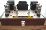
I'm attaching a couple of pictures. Hopefully you guys can give me some advice.


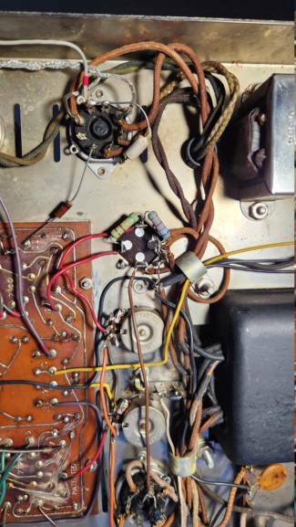
I'm attaching a couple of pictures. Hopefully you guys can give me some advice.