The Dynaco Tube Audio Forum

Would you like to react to this message? Create an account in a few clicks or log in to continue.
The Dynaco Tube Audio Forum

Dedicated to the restoration and preservation of all original Dynaco tube audio equipment - Customer support for Tubes4hifi VTA tube amp and preamp kits and all Dynakitparts.com products


+6
Njrob
jasn54
matheo
Roy Mottram
truebluephil
itrfguy
10 posters

    Digital bias meters

    itrfguy
    itrfguy


    Posts : 22
    Join date : 2020-10-26
    Location : Lehigh Acres, FL

    Digital bias meters Empty Digital bias meters

    Post by itrfguy Thu May 25, 2023 4:52 pm

    Got a bit tired of breaking out the Fluke to check the bias on these tubes.  A little engineering, a few ordered parts, and here's my new bias meters.

    Digital bias meters New_me10

    aguaazul, Dave_in_Va, stevebro, truebluephil, 10-E-C and Dale Stevens like this post

    avatar
    truebluephil


    Posts : 17
    Join date : 2013-07-01

    Digital bias meters Empty Re: Digital bias meters

    Post by truebluephil Fri May 26, 2023 12:54 pm

    itrfguy wrote:Got a bit tired of breaking out the Fluke to check the bias on these tubes.  A little engineering, a few ordered parts, and here's my new bias meters.

    Digital bias meters New_me10

    I would like to do the to mine. can you share with us the parts and what you had to do to make this happen.
    thx
    Phil

    Dale Stevens likes this post

    itrfguy
    itrfguy


    Posts : 22
    Join date : 2020-10-26
    Location : Lehigh Acres, FL

    Digital bias meters Empty Digital meter build

    Post by itrfguy Fri May 26, 2023 5:14 pm

    Disclosure:  This build works on MY modified ST-70, with KT66s.  I can not be responsible for damage to your equipment due to different components.  Proceed at your own risk.

    Here's a list of parts:
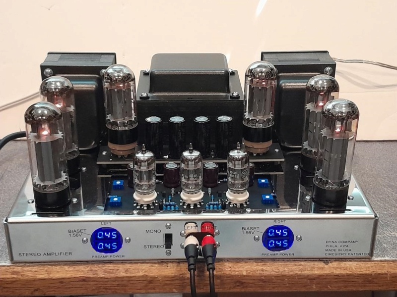
    4 - 0.28" LED DC 0-100V 3 Wires Digital Voltmeter Display  (found on ebay, $.99 each plus shipping from China)
    4 - 680uf 16v electrolitic capacitors
    1 - 1K ohm 1/2 watt resistor  (resistance can vary for desired brightness)
    1 - 2 terminal stand off  
    1 - 9vdc power supply  (I used a .35 amp wall wart) Each display needs a working current of greater than 20ma)
    2 - 1.25" x 2.5" x 1/16" tinted lexan rectangles.
    You'll also need to mount the power supply to the chassis and the displays to the lexan.  I used a hot glue gun.

    The build:
    1  - remove the two front mounted octal sockets and wiring.  In my case, I had to splice and heat shrink the filiment wires.
    2  - center the lexan pieces behind the front octal socket holes and trace the octal hole onto the lexan.
    3  - center and mount the LED displays onto the opposite side of the traced hole on the lexan with hot glue, silicone, epoxy, etc.
    4  - place the mounted display back into the front hole, center the displays, and mark the two mounting holes onto the lexan and remove.
    5  - drill the mounting holes, using a bit a size or two larger than your mounting screws, (this gives you some alignment adjustment) clean and mount the displays.
    6  - mount the 2 terminal standoff to one of the back driver board mounts.
    7  - mount the power supply. I hot glued the PS to the bottom half of the wall wart case, then glued the plastic case to the chassis.
    8  - solder the power supply AC input leads to the equipment side of the power switch and the equipment side of the fuse holder.
    9  - solder the hot DC lead to one side of the 2 terminal standoff and the ground lead to a chassis ground.
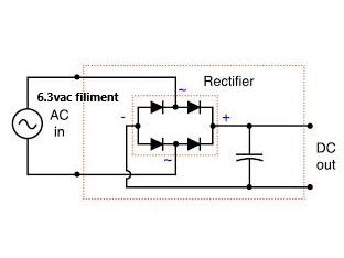
    10 - solder a 680uf capacitor to pin 8 of each output tube and ground, observing the polarity.  These act as a buffer to steady the display output.
    11 - solder the display yellow leads to pin 8 of each output tube.  I put my front tube up top and back tube on the bottom display.
    12 - solder the display red leads to the other side of the terminal standoff.  The 1K ohm resistor will mount between the terminals later.
    13 - solder the display black leads to a chassis ground.
    14 - tack solder the 1K ohm resistor between the 2 terminals on the standoff.

    Smoke test time
    Apply power to the amp.  Mine has a SSR and a delay circuit, but the LED displays will light up anyway.  If the displays are too dim for your taste, then power down, remove the 1K resistor and straight wire the 2 terminals.  Reapply power.  If the displays are too bright, then you can insert other values of resistors to get the brightness you prefer.  CAUTION!!  This resistor is limiting the current to the displays, ie, the lower the resistor value, the more current in the circuit and more heat in the resistor. Use the proper wattage to maintain a cool resistor.
    These displays can be calibrated using the pot on the back of each display and a trusted multimeter.  Mine are + or - .01 volts.

    Once you settle on the resistor that pleases you, solder it in properly.

    I've been running my amp for a few hours now and I haven't had, and hope not to have, any issues.  
    (You may want to wait before building this until I have several days on it. LOL)


    Digital bias meters Digita10


    Last edited by itrfguy on Mon May 29, 2023 7:31 pm; edited 2 times in total (Reason for editing : to include lexan thickness)

    stevebro likes this post

    avatar
    truebluephil


    Posts : 17
    Join date : 2013-07-01

    Digital bias meters Empty Re: Digital bias meters

    Post by truebluephil Fri May 26, 2023 6:13 pm

    thx for sharing your mod. I will wait a days like you suggested to make sure no issues occur.
    Phil

    itrfguy likes this post

    Roy Mottram
    Roy Mottram
    Admin


    Posts : 1839
    Join date : 2008-11-30

    Digital bias meters Empty Re: Digital bias meters

    Post by Roy Mottram Sun May 28, 2023 8:21 pm

    Hello itrfguy,
    very nice job, I may order these parts and try to make up kits or ready to install for lots of Dynaco people.
    Can you attach or email me a photo of the INSIDE of the FRONT panel (doesn't show in your photo) so I can get a better idea of how you did this
    and the size of the meters and mounting hardware. Thanks
    Roy info@tubes4hifi.com
    itrfguy
    itrfguy


    Posts : 22
    Join date : 2020-10-26
    Location : Lehigh Acres, FL

    Digital bias meters Empty Re: Digital bias meters

    Post by itrfguy Sat Jun 10, 2023 9:59 pm

    I've been running this mod without problems for weeks now, so have a go at it if you wish.  Roy has kits availible at their store (tubes4hifi.com).  Lots of possibilites for original driver boards and VTA boards, ST series, MKs, etc.  It's not rocket science, just electronics.  I'll be around to help if needed.
    itrfguy
    itrfguy


    Posts : 22
    Join date : 2020-10-26
    Location : Lehigh Acres, FL

    Digital bias meters Empty Re: Digital bias meters

    Post by itrfguy Tue Jun 13, 2023 4:15 pm

    If the power supply is an issue, you can build your own with diodes and a filter capacitor, and use the 6.3vac filiment voltage as the source.  Since you're only working with 6.3vac, your choices for diodes are pretty open.  The cap?  Some diagrams show a 100uf on the output, some show 470uf.  The formula is: C = I / (2 x f x Vpp) if you want to get dead accurate.  This cap filters out the ripple in the DC output of the rectifier by charging on the positive side of the ripple, then discharging on the negative side, providing a smoother DC output.

    Digital bias meters Rectif11

    Here's a simple power supply using 4 1N4007 diodes, a 100uf 35v cap, and a 5 post terminal strip.  There's the option for a dimming resistor between the red+ and the open post.

    Digital bias meters Led_pw10


    Last edited by itrfguy on Fri Aug 18, 2023 5:07 pm; edited 1 time in total
    avatar
    matheo


    Posts : 5
    Join date : 2010-11-07

    Digital bias meters Empty Issue

    Post by matheo Tue Jul 04, 2023 1:19 pm

    I decided to duplicate your project with my ST120 by purchasing the various parts on my own. I am having issues where the meters are not displaying the voltage properly. It end up with a continuous reading of 000V but then occasionally (every 5 secondes) will flash the correct bias reading but drop back to 000 volt. Not sure what is going on here. The amp has the delay board. The power supply I installed for the meters is a steady 9 volts.
    Roy Mottram
    Roy Mottram
    Admin


    Posts : 1839
    Join date : 2008-11-30

    Digital bias meters Empty Re: Digital bias meters

    Post by Roy Mottram Tue Jul 04, 2023 1:32 pm

    Matheo,
    you're not giving much info on your hookup, I'd guess you didn't use the capacitors or you have a bad connection somewhere.
    avatar
    matheo


    Posts : 5
    Join date : 2010-11-07

    Digital bias meters Empty Re: Digital bias meters

    Post by matheo Tue Jul 04, 2023 1:39 pm

    I hooked up all the same parts listed in this post including the capacitors. I am wondering if I got a ground loop issue.
    avatar
    matheo


    Posts : 5
    Join date : 2010-11-07

    Digital bias meters Empty Re: Digital bias meters

    Post by matheo Tue Jul 04, 2023 2:18 pm

    Please confirm installation of the capacitors. Positive leg (longer leg) on pin 8 and negative to ground?
    itrfguy
    itrfguy


    Posts : 22
    Join date : 2020-10-26
    Location : Lehigh Acres, FL

    Digital bias meters Empty Re: Digital bias meters

    Post by itrfguy Tue Jul 04, 2023 9:31 pm

    Yes, the positive lead of the 680uf 16v capacitor goes to pin 8 of the output tube and negative goes to ground, basically parallel to the 10 ohm resistor.  If it's still gives you problems, post a pic and we'll see if we can find the issue.
    avatar
    matheo


    Posts : 5
    Join date : 2010-11-07

    Digital bias meters Empty Re: Digital bias meters

    Post by matheo Sat Jul 08, 2023 12:01 am

    Update. Here we go, I thought for a moment I was going stupid. The issue I came across was that the voltage drop across the resistor was too low (below 3 volts). One would think this should not damage the LED voltmeter but it did. After removing and testing the meters, they would read too high on a two wire set up and would display 000 on a three wire set up. I know you can fry the meters if you apply too high of a voltage but be aware that applying too low a voltage can also affect the meters. Got some new meters, removed the resistor and ended up with 12 volts as a power supply. Reinstalled new meters and all is working as it should. Thanks all for the support and thank you to share this mod.

    itrfguy likes this post

    avatar
    matheo


    Posts : 5
    Join date : 2010-11-07

    Digital bias meters Empty Re: Digital bias meters

    Post by matheo Sat Jul 08, 2023 1:41 pm

    Final work
    Digital bias meters Image10

    itrfguy likes this post

    itrfguy
    itrfguy


    Posts : 22
    Join date : 2020-10-26
    Location : Lehigh Acres, FL

    Digital bias meters Empty Re: Digital bias meters

    Post by itrfguy Sun Jul 09, 2023 11:13 am

    Lookin' good!!
    Roy Mottram
    Roy Mottram
    Admin


    Posts : 1839
    Join date : 2008-11-30

    Digital bias meters Empty Re: Digital bias meters

    Post by Roy Mottram Fri Jul 14, 2023 8:31 pm

    I was originally running this mod using 7vdc derived from the 6vac filaments, and using 470 ohm resistors to reduce brightness,
    but the display wasn't always accurate and sometimes not even working.
    I changed the main capacitor from 100uF to 470uF, and removed all of the 470 ohm resistors, now the display is a little bright
    but they now read correctly and reliably.    See photo below.   This amp also has the dual rectifier mod.

    Digital bias meters Dr612

    itrfguy likes this post

    avatar
    jasn54


    Posts : 51
    Join date : 2015-04-13

    Digital bias meters Empty Re: Digital bias meters

    Post by jasn54 Thu Jul 27, 2023 6:07 pm

    I like this a lot, intial over-brightness aside, but would also be a little concerned about the LCDs dimming over time... (like the confounded display on my oven!). Is the dimming over time due to the display itself or degredation of the caps driving them?
    Njrob
    Njrob


    Posts : 50
    Join date : 2022-05-14
    Location : Nj

    Digital bias meters Empty Video of digital bias meters

    Post by Njrob Thu Aug 03, 2023 1:44 pm

    Shoutout to ltrfguy and tubes4hifi


    Last edited by Njrob on Thu Sep 28, 2023 11:22 am; edited 1 time in total

    erniegiro and itrfguy like this post

    Njrob
    Njrob


    Posts : 50
    Join date : 2022-05-14
    Location : Nj

    Digital bias meters Empty Re: Digital bias meters

    Post by Njrob Thu Aug 03, 2023 5:43 pm

    Ok


    Last edited by Njrob on Thu Sep 28, 2023 11:23 am; edited 1 time in total

    itrfguy likes this post

    Briansilcox
    Briansilcox


    Posts : 5
    Join date : 2023-01-10

    Digital bias meters Empty Meter kit

    Post by Briansilcox Sun Aug 06, 2023 10:11 am

    I just completed the meter kit installation ordered from Roy.  I paralleled the 470 ohm resistors per recommendation in the instruction sheet, with excellent brightness result.  This was an excellent upgrade for simple full time monitoring of bias drift.  I like the idea of the mirror tint, but will likely not remove the meters now.Digital bias meters 20230810

    knotscott, itrfguy and Njrob like this post

    itrfguy
    itrfguy


    Posts : 22
    Join date : 2020-10-26
    Location : Lehigh Acres, FL

    Digital bias meters Empty Reply to jasn54

    Post by itrfguy Thu Aug 10, 2023 10:11 am

    The life of the LED is related to the current applied.  Using the formula, I = E/R, as we increase the resistance of the circuit, it's current decreases.  Less current, longer life.  Here's a couple of practices I found on extending LED life:

    Reducing the supplied current and running them at below-rated output you can extend the lifetime considerably.

    Good thermal design that ensures the LED stays cool will also extend the LED lifetime.

    In my setup, I put a load resistor between the power supply and the red wires of the LED display units.  This increases total resistance of the circuit and decreases the current to each display, dimming them.

    And LEDs do dim as they age, so by applying the above practices will give your display a longer life.
    avatar
    cgtayloriii


    Posts : 5
    Join date : 2018-08-20

    Digital bias meters Empty Are Bias Meters Not Accurate?

    Post by cgtayloriii Sun Sep 24, 2023 3:48 pm

    I purchased the Tubes4HiFi Bias Meter Kit, and noticed that the instructions say "A DMM should still be the ultimate tool for setting bias." Why is this? Are the meters in the kit not accurate enough to set bias without using an additional DMM?
    itrfguy
    itrfguy


    Posts : 22
    Join date : 2020-10-26
    Location : Lehigh Acres, FL

    Digital bias meters Empty Re: Digital bias meters

    Post by itrfguy Sun Sep 24, 2023 4:30 pm

    It would be wise to calibrate your meters with a trusted DMM and check that calibration from time to time. Components have manufactured tolerances and I'm not familiar with the tolerances of the tubes4hifi kit or the build instructions. My meters are calibrated to +/- .01 volts, which is ok with me. If you have other questions or need assistance, please don't hesitate to ask.
    Roy Mottram
    Roy Mottram
    Admin


    Posts : 1839
    Join date : 2008-11-30

    Digital bias meters Empty Re: Digital bias meters

    Post by Roy Mottram Mon Sep 25, 2023 2:09 pm

    there's a big difference in quality and accuracy between meters that cost $1 each and meters that cost $50-200 each.
    These meters will provide a good indication of bias, but they don't have the resolution and accuracy of a $50 DVM.
    Especially trying to measure a small amount of voltage (1/2 vdc or less). Their resolution will not give you 1/100 of a volt steps like a good DVM.
    But even if the meters are reading 0.45vdc instead of 0.40vdc, you will still notice if that changes from 0.45 to 0.50v or to 1.00v which is obviously a problem
    with the bias changing on your amp.
    These are aimed at people who don't bother to pull their meter out every week and check all four output tubes.
    With these meters, your bias on each output tube will be starring you in the face every time the amp is on.

    itrfguy and Briansilcox like this post

    erniegiro
    erniegiro


    Posts : 22
    Join date : 2020-08-07
    Location : Atlanta, GA USA

    Digital bias meters Empty Re: Digital bias meters

    Post by erniegiro Mon Sep 25, 2023 11:20 pm

    Njrob, I like the looks of the mirror film. What type is it? I've searched Amazon and found some static cling mirrored sun film meant for windows, is this what you used?

    Thanks

    Errnie

    Sponsored content


    Digital bias meters Empty Re: Digital bias meters

    Post by Sponsored content


      Current date/time is Sat Apr 27, 2024 4:36 pm