Would you like to react to this message? Create an account in a few clicks or log in to continue.
The Dynaco Tube Audio Forum
Dedicated to the restoration and preservation of all original Dynaco tube audio equipment - Customer support for Tubes4hifi VTA tube amp and preamp kits and all Dynakitparts.com products
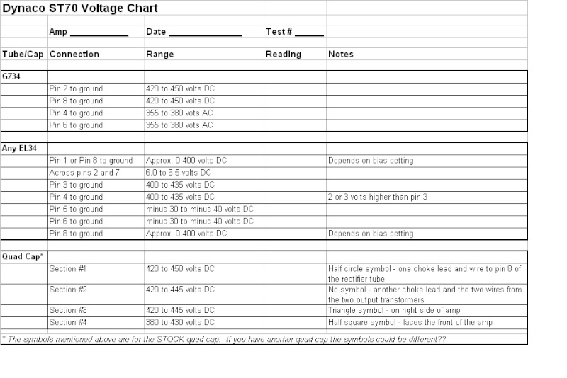
I took Bob's ST70 Voltage Chart from another post and put into an EXCEL spreadsheet for easier use, however I can't figure out how to attach it as a spreadsheet.
At any rate, here is an image of the chart. If anyone wants a copy of the original send me an email and I'll get a copy off to you. Please let me know if there are any corrections.
Below are the voltage readings for the ST-120 amp kit
GZ34 or solid state rectifier Pin 4 to ground – 400 - 425 volts AC Pin 6 to ground – 400 - 425 volts AC Pin 2 to ground – 490 – 530 volts DC * Pin 8 to ground – 490 – 530 volts DC *
Any 6550/KT88 Pin 1 to ground – approx .550 volts DC (depends on bias setting) Across pins 2 and 7 – 6.0 – 6.5 volts AC Pin 3 to ground – 470 - 520 volts DC * Pin 4 to ground – 470 - 520 volts DC * Pin 5 to ground – minus 50 to minus 62 volts DC Pin 6 to ground – minus 50 to minus 62 volts DC Pin 8 to ground – approx .550 volts DC (depends on bias setting)
Quad cap Section # 1 (SQUARE symbol) ---------- 480 – 530 volts DC * Section # 2 (HALF CIRCLE symbol) ----- 470 – 525 volts DC * Section # 3 (NO symbol or CIRCLE) ---- 470 – 525 volts DC * Section # 4 (TRANGLE symbol) --------- 400 – 440 volts DC *
Central 12AT7 – Pin 1 or pin 6 to ground > 130 – 175 volts DC * Two outer 12AT7’s – Pin 1 or pin 6 to ground > 255 – 295 volts DC * Any 12AT7 – across the two incoming heater wires > 6.0 - 6.5 volts AC “-50 VAC” on driver board > 48 – 58 volts AC “B+” on driver board > 400 – 440 volts DC *
* means that the voltage readings will be near the top end of the scale if you use a solid state rectifier
Bugs wrote:I took Bob's ST70 Voltage Chart from another post and put into an EXCEL spreadsheet for easier use, however I can't figure out how to attach it as a spreadsheet.
At any rate, here is an image of the chart. If anyone wants a copy of the original send me an email and I'll get a copy off to you. Please let me know if there are any corrections.
shouldnt the pins on the diagram for EL34 2-7 be AC vice DC?
Last edited by jrubin on Sun Oct 04, 2015 1:23 pm; edited 1 time in total (Reason for editing : typo)
Yes - on the original Dynaco ST-70, VTA ST-70, VTA ST-120 and VTA M-125's, the heater wires are all AC voltages. There is a "bug" in Bugs Excel spreadsheet under "Any EL34 across pins 2 and 7" (pun intended). It should read "6 to 6.5 AC voltage." Also keep in mind that if your incoming AC line voltage is much above 120 VAC, the upper limit can rise to near 7.0 VAC
Since we are on the topic of ST70 voltages, I wanted to make sure of the B+ current draw the VTA board. I calculated about 23 mA by measuring the difference between the EL34 B+ and the board B+ across the 2.2 k resistor. Is this correct?
Since we are on the topic of ST70 voltages, I wanted to make sure of the B+ current draw the VTA board. I calculated about 23 mA by measuring the difference between the EL34 B+ and the board B+ across the 2.2 k resistor. Is this correct?
Thanks
I honestly have never measured the current draw of the VTA driver board ? Roy may know ? If he sees this, he will probably comment on your question.
Can someone point me to some details as to how these readings are taken - as in do I remove the tube and take the reading from the top or do I have to leave the tube in place and measure from under the chassis?
However, If all tubes EXCEPT the rectifier tube are in, there will be no B+ (high voltage DC to the plates of any of the 7199's or EL34's) That means no DC voltages on the quad caps No DC on the tube rectifier output (obviously) No DC to the other tube plates and that also means no current to set the bias for on the EL34's
The lower negative DC voltages come from the selenium rectifier for negative bias and will be present even without the tube rectifier..
If you are running a selenium rectifier, and you have measured the correct input voltage as described below you should see 50VAC in on the bottom lug and -65VDC on the top lug. When measuring Id advise you put a piece of electrical tape on the chassis (while powered off) under the lugs so you dont short the AC side to the chassis.
Also consider that if tubes are missing and there is less load, then the voltages that do exists will be higher that they should be
If this is a baseline test, be advised that if the tube rectifier is in, the bias should be set correctly before you spend any length of time troubleshooting Also, be sure the quad cap is good before putting in the tube rectifier, or bad things could happen
These values also assume the correct input voltage from your mains. The assumption in the manual is that you have 117VAC, which probably isnt the case.
If you have a variac, a good trick is to test an AC connection on the rectifier socket (pin 4 or pin 6 to chassis), and adjust the variac till you see 360VAC from that socket to ground when that is achieved, look at the voltage of the incoming ac into the primary of the power transformer. If it shows 117VAC, then you have a 117VAC transformer, 120 and you have a 120 and so on.
When this method is achieved, you should also see 6.3 to 6.4VAC on the EL34 heaters (across pin 2 and7) of any el64
I made a series of movies as I work through the baseline of an old st70 that I am currently working on....