The first thing that caught my attention as I got ready to begin this build was the very high quality of the PCB.

This thing is really thick and sturdy as well as double sided. It has plated through holes with pads on both sides and is beautifully printed. Because of the thickness and different sizes of the holes component leads it took me a few components to get the soldering iron temperature just right. At first it was too cool and after I got the solder to flow it was layering on the opposite side of the board.
I am typically an over-engineer-er and err on the maybe-too-much-solder end of the spectrum, and I had a real tough time (given my relative inexperience) having a consistent finished look on the opposite side of the board.
Here it is with resistors installed:
Although the instructions suggested soldering the components in from their top side, I chose to solder on the bottom, as I'd rather have the flux splashes and marks on the underside and out of sight.
I decided to install the resistors with the tolerance color band uniformly to the right and oriented the Dale/Vishay and PRP resistors so that the values were easily visible and facing the same direction. (Who knows when I might have to trouble shoot???

)
You'll notice that the resistors aren't installed in the top left High Voltage B+ area of the board. These are unnecessary because of the tube rectifier option that I will be using with this pre. (The diodes in that area are left out as well.)
R18 is not yet installed because a design change from Roy's PCB supplier created a need for two R18s in this circuit rather than one and I am waiting for the part to arrive.
On a totally dorky note, one of the resistor values is 909 ohm. This immediately got The Beatles singing "One After 909" in my head and that kept me haunted for the rest of the evening while I worked. (And typing about it has done it again...so great.)
Next went in the diodes and tube sockets:
I installed the diodes, being careful to orient them properly.
The quality ceramic tube sockets went in very easily, without any bending or adjusting and getting them level and aligned was almost effortless. I first soldered pin 5 on each socket, checked them for levelness and "twistedness," and soldered in pins 1 and 9. From there, I made sure that they were all exactly where I wanted them and then soldered in the rest of the pins.
I next installed the capacitors, starting with the lowest profile components and working to the tallest.
The white ones are the upgraded SoniCaps and I got so excited about getting them in that I had to go back and put in the little 1000pF guys that reside in the heater voltage section of the circuit back in the right hand corner...lest my anal mind do things out of order and eventually explode.

After I got the other axial caps installed I moved to the radials in the heater voltage section. (Brown ones.) Because this PCB can be used for several different circuits, there are two options for the orientation of C12 and C13. I studied the schematic and the PCB circuit and it looked to me like the orientation should be left to right. I confirmed with Roy and had myself a "I actually am learning something!" moment.
Here are the photos as I added the rest of the capacitors:
 From there it was a simple matter of getting in the heater voltage regulator and heatsink:
It is easier to install the regulator and heatsink all as one piece and Roy sends it already together. I had to muscle the heatsink in there and it was a little scary, but it worked out fine. I soldered it in and there you have it!
After one last look to double check the symmetrical consistency, my next step will be to install the jumpers and the R18 resistors and then get started on the phono stage.
My future posts won't be this long as I built more than I posted but am now caught up, so I promise not to be so tedious on your brain from here on out.
BUT one more thing...
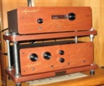
Roy has the chassis made to order, so the cool thing about it was I got to choose if I wanted a tape loop and mute switch. Roy sent me pics and we talked about my needs and then off the chassis went to be drilled and printed. I thought that was the bee's knees, man! (I always wanted to say that.) It should be ready sometime this week and am really jacked to get it.
So thanks for following along and feel free to comment and suggest, I'm in this to learn, have fun, and listen to great music.
Cheers,
Ed