The Dynaco Tube Audio Forum

Would you like to react to this message? Create an account in a few clicks or log in to continue.
The Dynaco Tube Audio Forum

Dedicated to the restoration and preservation of all original Dynaco tube audio equipment - Customer support for Tubes4hifi VTA tube amp and preamp kits and all Dynakitparts.com products


+9
quad
Luddite
anbitet66
j4570
Roy Mottram
SuperB
Bob Latino
burnedfingers
bktheking
13 posters

    St-70 upgrades

    avatar
    bktheking


    Posts : 51
    Join date : 2011-12-20

    St-70 upgrades Empty St-70 upgrades

    Post by bktheking Mon Jan 02, 2012 1:17 am

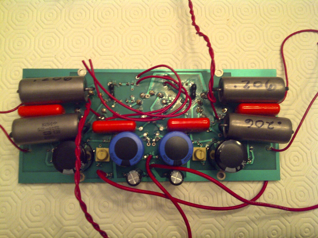
    Hey folks, new to the forum and just wanted to say hello and tell you about my upcoming st-70 rebuild and upgrades and had a question. I have purchased the high gain vta board with all the upgrades and I have the opportunity to buy the sds labs cap board as well. Looking at the schematics there is an option for bias in and out which i'm not sure i'll need cause the the VTA board already has provisions for individual tube bias. There are no real instructions on how to install this board, I understand the 4 wires from the old cap and where they would go, the ones I don't understand are 2 x filament center taps and transformer bias winding, what wires are these?

    Many thanks

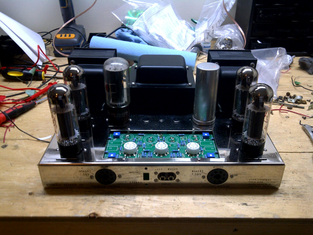
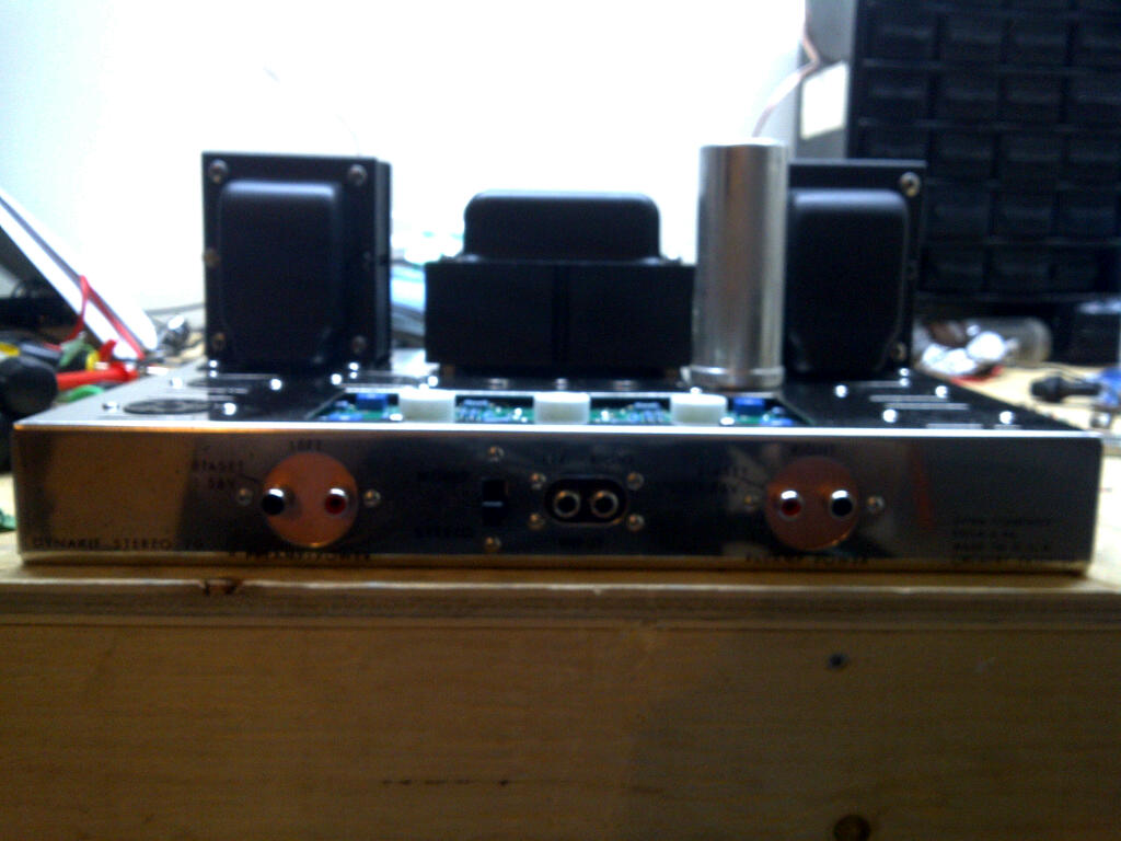
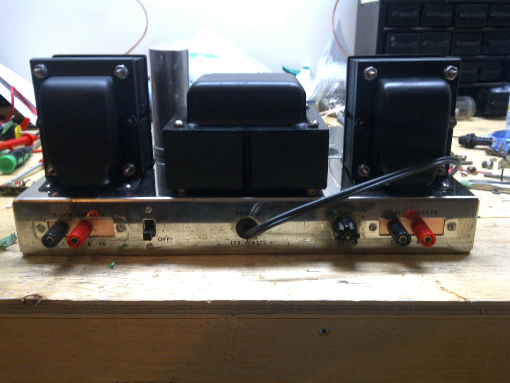
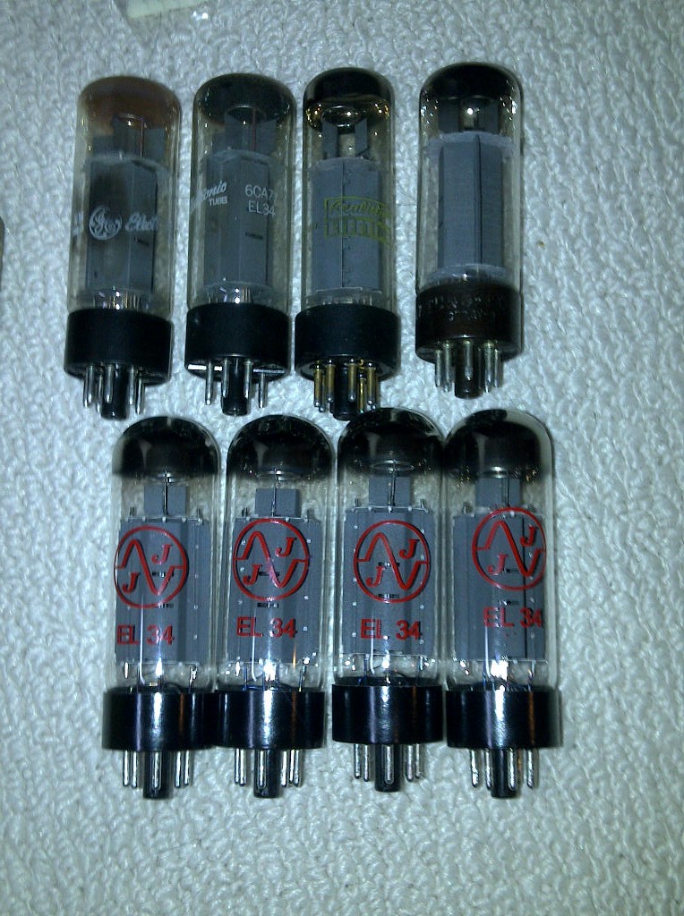
    Pics will be posted as soon as i'm under way.


    avatar
    burnedfingers


    Posts : 29
    Join date : 2009-05-06

    St-70 upgrades Empty Re: St-70 upgrades

    Post by burnedfingers Mon Jan 02, 2012 8:50 am

    The SDS labs board does contain ALL the necessary information to install it in your Dynaco Stereo 70 unless the board is used and the information has been lost. It is very easy to use the on board bias circuit on the SDS board and the 4 bias adjustable pots on the VTA board.St-70 upgrades Sds_la19
    Bob Latino
    Bob Latino
    Admin


    Posts : 3263
    Join date : 2008-11-26
    Location : Massachusetts

    St-70 upgrades Empty Re: St-70 upgrades

    Post by Bob Latino Mon Jan 02, 2012 9:30 am

    If you install the SDS board into an ST-70 with the VTA driver board I would use the bias system on the VTA driver board. The bias system on the SDS board is set up for TWO bias pots while the VTA driver board has FOUR bias pots. To answer your questions.

    1. The RED/BLACK wire from the power transformer is the bias winding. Connect this directly to the "-50 VAC" eyelet on the back edge of the VTA driver board.

    2. The GREEN/YELLOW and the BROWN/YELLOW wires from the power transformer are the 2 X filament center taps. These two wires will now connect to the two "FCT" eyelets on the SDS cap board.

    Bob
    avatar
    burnedfingers


    Posts : 29
    Join date : 2009-05-06

    St-70 upgrades Empty Re: St-70 upgrades

    Post by burnedfingers Mon Jan 02, 2012 9:44 am

    Quote
    If you install the SDS board into an ST-70 with the VTA driver board I would use the bias system on the VTA driver board. The bias system on the SDS board is set up for TWO bias pots while the VTA driver board has FOUR bias pots. To answer your questions.

    Actually the SDS board has terminals for right and left lug of the pot and its very easy to parallel to the large pots if you already have them on your Dynaco. Most are only drilled for the original two bias pots however. Some like my Dynaco have been drilled for two additional pots.

    Your right in one respect. If you don't plan on modifying your Dynaco then by all means use the whole bias circuit on the VTA board. People like myself that modify and modify and modify will choose to use the portion on the SDS board that contains the bias resistors and the reason is for easy changing of the bias circuit for running say KT88's or 6BG6GA's which I don't believe the bias circuit on the VTA board will allow without a resistance change. Its easier in my opinion to change resistors on the SDS board instead of doing so on the VTA board. Not saying it can't be done but it might be easier removing a resistor from a board without possible feed thru connections so that there is no damage to the PC board traces.
    Bob Latino
    Bob Latino
    Admin


    Posts : 3263
    Join date : 2008-11-26
    Location : Massachusetts

    St-70 upgrades Empty Re: St-70 upgrades

    Post by Bob Latino Mon Jan 02, 2012 10:03 am

    Re: Your last paragraph which states ..

    "Its easier in my opinion to change resistors on the SDS board instead of doing so on the VTA board. Not saying it can't be done but it might be easier removing a resistor from a board without possible feed thru connections so that there is no damage to the PC board traces."

    The only resistor you ever have to possibly change out on the VTA driver board is the main bias resistor. Sometimes if you use certain brands of KT88 tubes this 10K resistor might have to be pulled for a resistor of a lower value. (7.5K works good) The instructions on the VTA amp kits specifically state that this resistor (R39) is to be put on the BOTTOM of the driver board to make it easier to change out if needed.

    Another thing RE: your statement > "so that there is no damage to the PC board traces" You CAN damage solder traces on the SDS board. On the SDS board the top has sealed solder traces but the bottom of the SDS board does not have sealed solder traces. On the VTA driver board the solder traces are sealed top AND bottom and there are plated through eyelets. There is no danger of solder traces lifting on the VTA driver board but there is a danger on the SDS board of a solder trace lifting on the bottom due to excessive soldering iron heat and/or repeatedely changing out components on the board.

    Bob
    avatar
    burnedfingers


    Posts : 29
    Join date : 2009-05-06

    St-70 upgrades Empty Re: St-70 upgrades

    Post by burnedfingers Mon Jan 02, 2012 10:11 am

    Its been a few years since I owned a VTA driver board and I didn't remember that it was that easy to perform the bias resistor change. I stand corrected... no offense meant.

    I generally will parallel another resistor on the SDS board to lower the resistor value until I come up with something that will allow me the flexability I need and then possibly change the resistor to the value I need.
    Bob Latino
    Bob Latino
    Admin


    Posts : 3263
    Join date : 2008-11-26
    Location : Massachusetts

    St-70 upgrades Empty Re: St-70 upgrades

    Post by Bob Latino Mon Jan 02, 2012 10:25 am

    Yes - Paralleling resistors does work OK also on altering the bias resistor's value. If you use KT88 tubes in a VTA ST-70 they will bias well over to one side (the right side) of the bias pot's range. You can, as you mention, parallel another resistor with the 10K that is already there to get a lower equivalent value resistor. This will allow biasing KT88's more towards the center of the bias pot's range.

    Bob
    avatar
    bktheking


    Posts : 51
    Join date : 2011-12-20

    St-70 upgrades Empty Re: St-70 upgrades

    Post by bktheking Tue Jan 03, 2012 11:16 am

    The DC board doesn't look like the pic, I think it's older but same idea. Thanks for the info Bob, I will wire it up as soon as I get my parts.
    avatar
    SuperB


    Posts : 15
    Join date : 2012-01-01

    St-70 upgrades Empty Re: St-70 upgrades

    Post by SuperB Wed Jan 04, 2012 5:45 am

    My friend lent me his VTA ST-70 just 2 days ago that he bought several years ago and he ends up having a new chassis with hardwire all the way. I had conversation with him about his VTA ST-70. He has high gain version, and then switched to low gain after Roy Mottram sending him the new parts list for the low gain version. I asked him about SDS labs board since I want to try on my stock unit. He said the SDS labs modules is ok but end up having his favorite cap (Kendeil) in the VTA circuit and all coupling cap upgrade to PSVANE copper/teflon cap. He said quantity not necessary equal to quality. Good quality electrolytic will benefit to the sound due to lowest ESR and impedance. He has tried different electrolytic and found he loves the Kendeil the most.

    This VTA amplifier didn't play for a while and in the storage since my friend / coworker has so many amplifier. I let it cook. The midrange is not as romantic as my stock Dynaco 70, but still very very good and the high is very extended. Therefore, I prefer to try some quality electrolytic on the VTA board rather than getting the SDS labs board. His VTA amplifier truly reference grade amplifier.

    Since it has a switch on his unit for UL/triode operation. This is the next thing I'm going to try! But worry not enough power for my LS3/5A system.
    Roy Mottram
    Roy Mottram
    Admin


    Posts : 1839
    Join date : 2008-11-30

    St-70 upgrades Empty Re: St-70 upgrades

    Post by Roy Mottram Wed Jan 04, 2012 7:37 pm

    Hi SuperB,
    it sounds like you've gotten used to the very romantic surupy favor of the original ST70 compared to the more accurate VTA mod which has a neutral sound. You should swap in some Mullard or Telefunken tubes and swap out the output coupling caps for some PIO caps.
    For the low gain version, old RCA 12AU7 "clear tops" also sound very good and much less costly. I've got several if you need any.
    Both of those changes will make much more difference than changing any of the power supply caps.
    avatar
    bktheking


    Posts : 51
    Join date : 2011-12-20

    St-70 upgrades Empty Re: St-70 upgrades

    Post by bktheking Wed Jan 04, 2012 10:21 pm

    Here is the board i got, i didn't do the solder work so I hope it works. Dc board is on route.

    St-70 upgrades Img2012010400280


    St-70 upgrades Img2012010400279

    Im supposed to also have the cover hence the caps on the bottom, its on route too as the seller forgot to ship it.
    Roy Mottram
    Roy Mottram
    Admin


    Posts : 1839
    Join date : 2008-11-30

    St-70 upgrades Empty Re: St-70 upgrades

    Post by Roy Mottram Wed Jan 04, 2012 11:22 pm

    just make sure those big caps on the bottom are insulated from the board and from anything else
    avatar
    bktheking


    Posts : 51
    Join date : 2011-12-20

    St-70 upgrades Empty Re: St-70 upgrades

    Post by bktheking Mon Jan 09, 2012 2:43 pm

    Well here it is, picked it up today. It's dirty, first thing- transformers are coming off and the chassis is being polished.

    St-70 upgrades Img2012010900281
    avatar
    bktheking


    Posts : 51
    Join date : 2011-12-20

    St-70 upgrades Empty Re: St-70 upgrades

    Post by bktheking Wed Jan 11, 2012 12:07 pm

    Bob Latino wrote:If you install the SDS board into an ST-70 with the VTA driver board I would use the bias system on the VTA driver board. The bias system on the SDS board is set up for TWO bias pots while the VTA driver board has FOUR bias pots. To answer your questions.

    1. The RED/BLACK wire from the power transformer is the bias winding. Connect this directly to the "-50 VAC" eyelet on the back edge of the VTA driver board.

    2. The GREEN/YELLOW and the BROWN/YELLOW wires from the power transformer are the 2 X filament center taps. These two wires will now connect to the two "FCT" eyelets on the SDS cap board.

    Bob

    Looking at 1.- I should be putting the diode on a standoff between the transformer wire and the vta board correct?
    Bob Latino
    Bob Latino
    Admin


    Posts : 3263
    Join date : 2008-11-26
    Location : Massachusetts

    St-70 upgrades Empty Re: St-70 upgrades

    Post by Bob Latino Wed Jan 11, 2012 1:24 pm

    No - There is a spot on the VTA driver board called "D1" to mount the diode. Make sure when you install the diode that the banded end of the diode faces the "-50 VAC" eyelet.

    Bob
    avatar
    bktheking


    Posts : 51
    Join date : 2011-12-20

    St-70 upgrades Empty Re: St-70 upgrades

    Post by bktheking Wed Jan 11, 2012 2:29 pm

    I also noticed in the instructions I have to add 4 10ohm resisitors to the octals. Are these 1/2 watt?


    Thanks for your help Bob.

    Bob Latino
    Bob Latino
    Admin


    Posts : 3263
    Join date : 2008-11-26
    Location : Massachusetts

    St-70 upgrades Empty Re: St-70 upgrades

    Post by Bob Latino Wed Jan 11, 2012 2:59 pm

    On the 10 ohm resistors I would use at least 1 watt. On the VTA ST-70 amp kits, one 10 ohm 2 watt resistor is used on each of the four output tubes. On the original Dynaco ST-70 a single 5 watt resistor was used for TWO output tubes which equates to 2.5 watts per output tube.

    Some say to use a small (1/2 watt) resistor here because it can act like a fuse for that tube in case the tube develops a short. The thinking here is that the resistor will blow before the tube blows and the resistor is cheaper to replace than the tube. That 10 ohm bias resistor is that tubes only reference to chassis ground. If that resistor blows then the tube will stay lit but other than that, the tube won't be "in circuit". Personally, I don't agree with the "small bias resistor as a fuse for that tube" way of thinking. If the tube goes bad and the fuse blows because of excessive current draw - then the tube IS BAD and the TUBE should be replaced.

    Bob

    DougWHolt likes this post

    avatar
    bktheking


    Posts : 51
    Join date : 2011-12-20

    St-70 upgrades Empty Re: St-70 upgrades

    Post by bktheking Thu Jan 12, 2012 11:04 am

    Picked them (resistors) up today. Here's a couple of pics , the first is when I got it, the second is last night after reinstalling everything and doing some wiring, still have lots to do but it's coming along.

    St-70 upgrades Img2012010900281

    St-70 upgrades Img2012011100303

    DougWHolt likes this post

    Bob Latino
    Bob Latino
    Admin


    Posts : 3263
    Join date : 2008-11-26
    Location : Massachusetts

    St-70 upgrades Empty Re: St-70 upgrades

    Post by Bob Latino Thu Jan 12, 2012 1:19 pm

    Nice work .. Keep the photos coming .. I, as well as other Forum members, love to see older ST-70's rescued from the scrap heap and placed into daily use again ..

    Bob
    avatar
    bktheking


    Posts : 51
    Join date : 2011-12-20

    St-70 upgrades Empty Re: St-70 upgrades

    Post by bktheking Thu Jan 12, 2012 1:29 pm

    Just a note on the front octals. The vta board has the russian PIO caps. I like the look of the octals on the front but there just isn't enough room. I had to use electrical tape to prevent the russian caps from making contact with the octals. I'm now rethinking it and i'm going to install rca jacks instead because of the space issue.
    avatar
    bktheking


    Posts : 51
    Join date : 2011-12-20

    St-70 upgrades Empty Re: St-70 upgrades

    Post by bktheking Thu Jan 12, 2012 11:55 pm

    Bye bye octals

    St-70 upgrades Img2012011200308
    avatar
    j4570


    Posts : 150
    Join date : 2010-08-30

    St-70 upgrades Empty Re: St-70 upgrades

    Post by j4570 Fri Jan 13, 2012 8:47 pm

    I think it's possible to get the PIO caps in there, I did. But it's tight! I also did the soldering, and left the cap leads a little longer I think to bend them back out of the way.

    I like see them brought from the dead too. What kinda tubes (the rectifier in particular) are those?

    I take it you replaced the can capacitor???

    anbitet66
    anbitet66


    Posts : 143
    Join date : 2009-12-23
    Location : Valley Stream, NY

    St-70 upgrades Empty Re: St-70 upgrades

    Post by anbitet66 Fri Jan 13, 2012 9:23 pm

    Now I must ask; did you make the rca/octal socket replacements yourself or buy them? And are they for multiple inputs, and if so, how do you switch between the original input as well as the two new ones?
    avatar
    bktheking


    Posts : 51
    Join date : 2011-12-20

    St-70 upgrades Empty Re: St-70 upgrades

    Post by bktheking Fri Jan 13, 2012 10:14 pm

    Yes I made them for both the front bias measurement and rear binding posts. I took copper covered board which you can buy at any electronics parts store, used a hacksaw to cut out a square large enough to accommodate the hole. Then I placed the cut out behind the open octal hole and marked the screw holes and drilled. I used the ground loops that came with the RCA's to trace the holes for the rca connectors. Each RCA is running to the bias point to the front and rear tube, matched on both sides. When I want to measure each bias I will ground to the chassis and stick the probe onto the rca slightly to check bias. They aren't inputs at all, they are for bias measurement. The tubes are JJ's, new ones. The rectifier i'll have to check. I'm replacing the can with a SDS cap board. All screws have been replaced with allen head stainless steel screws less the ones for the VTA board and the transformers, they are a mixed bag due to size limitations in the allen head assortment.

    Here is the rear of the unit with the binding posts, new power cable and new power switch installed.

    St-70 upgrades Img2012011200306


    Last edited by bktheking on Fri Jan 13, 2012 11:15 pm; edited 2 times in total
    avatar
    bktheking


    Posts : 51
    Join date : 2011-12-20

    St-70 upgrades Empty Re: St-70 upgrades

    Post by bktheking Fri Jan 13, 2012 10:36 pm

    Here are the tubes that came with the unit, 4 brand new JJ's, 2 GE mullard made , 1 realistic lifetime and 1 tung sol. I also have two mismatched 7199's and the old board.

    St-70 upgrades Img2012010900284


    Here is the rectifier tube.

    St-70 upgrades Img2012011300311

    Here is my wiring up until now.

    St-70 upgrades Img2012011300310

    I'm hoping Bob can have a gander and give me the thumbs up, 1K resistors were replaced, the 15's were removed and new 10 ohm's on all 4 tubes were installed @ 1Watt rating. . All disconnected wires go to the DC board, everything else is wired up. Once I get my tubes and DC board installed and wired up I can fire it up.

    Sponsored content


    St-70 upgrades Empty Re: St-70 upgrades

    Post by Sponsored content


      Current date/time is Sat Apr 27, 2024 11:54 pm