From the AK forum, Kegger contacted me to do a PCB for a ST70 clone that he had designed around a low cost input tube. We tried to keep the same design configuration, with a little change in the feedback. The PCB is made by iron on toner transfer, etched in the sink. After a year of playing with a bunch of output tubes, B+ levels and output iron, the assembled design was B+470V, Svet6550=C= outputs and Hammond 4.3k 60watt outputs. I tried to upload pics, do not know if that was successful. I've been visiting this site for some time to learn more about the ST70, thanks to all that have posted.
4 posters
Home brewed ST70

GP49- Posts : 792
Join date : 2009-04-30
Location : East of the sun and west of the moon
- Post n°2
 Re: Home brewed ST70
roline wrote:I tried to upload pics, do not know if that was successful.
No. It wasn't. But you know that already!
Eagerly awaiting them, still!

roline- Posts : 3
Join date : 2010-08-20
- Post n°3
 upload attempt...
Pics of the home-brew ST70, bias LEDs let you know if there is a bias issue, tube going south.....

bias monitor turned off

bias monitor turned on
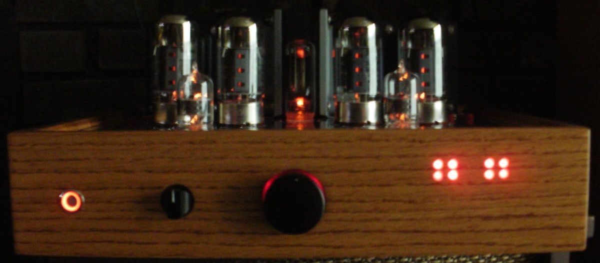

bias monitor turned off

bias monitor turned on


Bob Latino- Admin
- Posts : 3273
Join date : 2008-11-26
Location : Massachusetts
- Post n°4
 Re: Home brewed ST70
Hi Roline,
Nice job ... Any way you could post a photo of the interior wiring and maybe give some more info on the circuit/driver tubes used?
Bob
Nice job ... Any way you could post a photo of the interior wiring and maybe give some more info on the circuit/driver tubes used?
Bob

roline- Posts : 3
Join date : 2010-08-20
- Post n°5
 Re: Home brewed ST70
More pics of the development stage. KEGGER from the AK site supplied the original schematic that I started with and I did a few mods that resulted in the PCB that I fabricated. I played with different output tubes, power transformers and output iron. The lowest cost was with Russian 6P3S (6L6) tubes, sounded great with 6.6k outputs but ran out of steam with lower impedances. Russian 5881 (6L6) tubes were a great value for a higher B+, again they preferred 6.6k outputs. EL34,s, 6550, and KT88 could drive the 4.3 K outputs but sounded better with the 6.6k with less feedback. I played with UL and Triode mode, my favorite was with the Svet 6550=C= outputs in triode mode, 4.3K for a little higher output level.

The PCB is made by iron on toner transfer using high clay paper, etched in zip-lock bags in the sink. ( both sides) top is clear coated and the important through holes are bass grommeted.
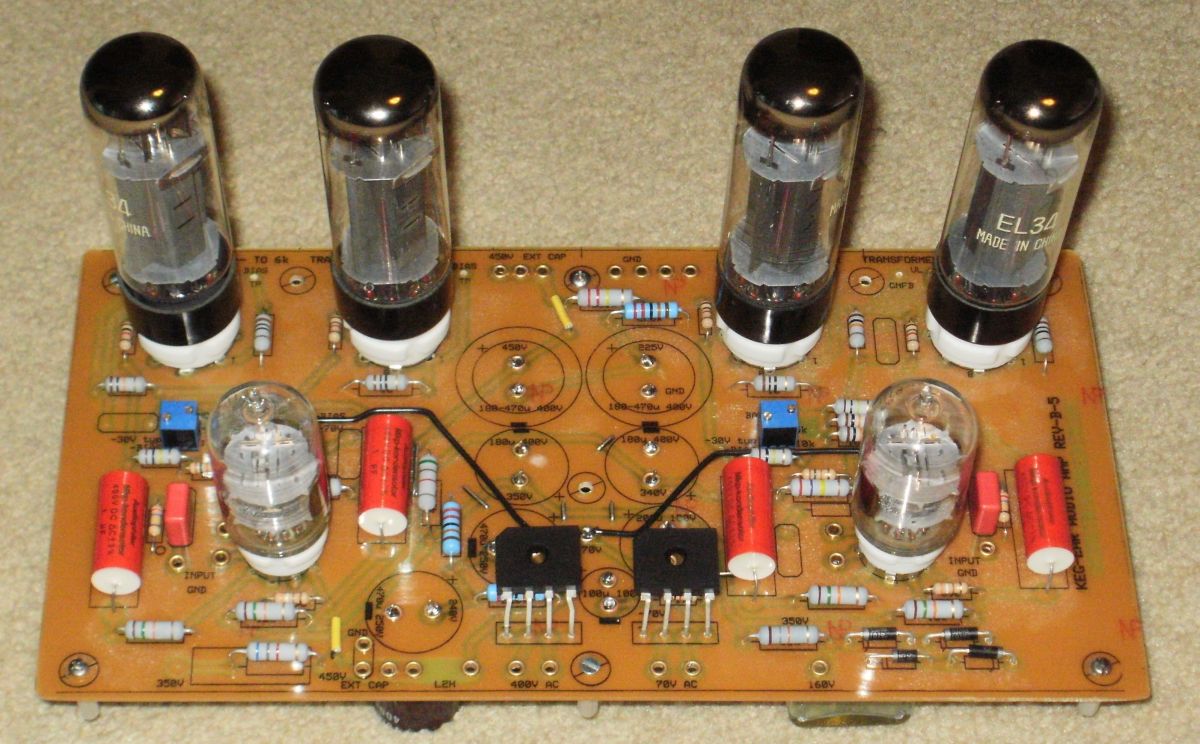
I use ground plane stitching to connect the grounds where separated by long traces to prevent ground loops. The electrolytic caps are mounted to the back side with the grommets. The second stage to output tube coupling was evaluated with Russian .33u PIO and 1u poly caps, I could not tell a difference between them.
First stage bias adjust, second stage bias and off-set adjustments are the 20 turn blue pots. The diode section on the lower right is for a 50 Volt tap for elevated heaters and the 150 is for nixie tube if utilized. I did not populate the 1st stage to second stage pole, it was stable without it. Feedback was just reduced to GNFB, 10k AND 100p in parallel.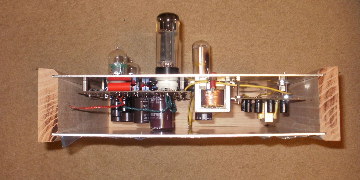
I added the LED bias monitor and added a power supply that bolts to the transformer mounting screws. It also powers a small 12v ventilation fan. Either can be turned on or off. The B+ is modified from the main board with an assembly comprised of the 6CG3 tube, diodes and stacked caps, inductor choke connections and secondary stacked cap PCB that feeds the back of the main PCB. I did not use the diode bridge that is in the front of the PCB ( optional connection). The damper diode is on its own heater transformer. The thought was if I needed more of a delay it would be easier to control the power to it.
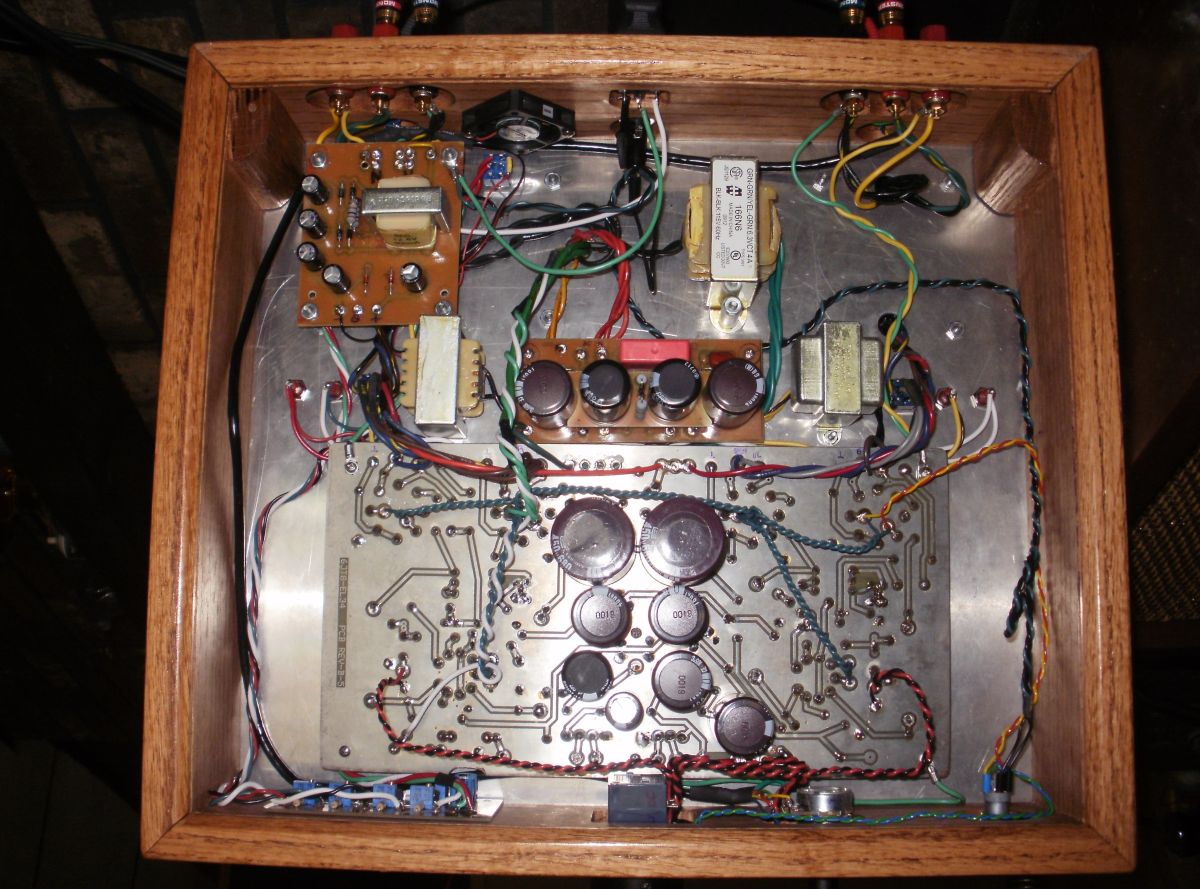
The choke was a standard choke that the "Magic Smoke Genie" escaped from in an earlier amp. I rewound it with a heavier gage wire to handle 300ma. I lost a little inductance in the process... The guts are not a pretty sight. That is one area that I still remain extremely challenged. I'm very envious of those that can make the inside look like a piece of art.
So in a nut shell, this is my interpretation of the ST70, same cathodyne phase stage, strong B+ supply, larger coupling caps, decent output tubes and 4.3K iron. A special thanks to KEGGER that got me started on this project.

The PCB is made by iron on toner transfer using high clay paper, etched in zip-lock bags in the sink. ( both sides) top is clear coated and the important through holes are bass grommeted.

I use ground plane stitching to connect the grounds where separated by long traces to prevent ground loops. The electrolytic caps are mounted to the back side with the grommets. The second stage to output tube coupling was evaluated with Russian .33u PIO and 1u poly caps, I could not tell a difference between them.
First stage bias adjust, second stage bias and off-set adjustments are the 20 turn blue pots. The diode section on the lower right is for a 50 Volt tap for elevated heaters and the 150 is for nixie tube if utilized. I did not populate the 1st stage to second stage pole, it was stable without it. Feedback was just reduced to GNFB, 10k AND 100p in parallel.

I added the LED bias monitor and added a power supply that bolts to the transformer mounting screws. It also powers a small 12v ventilation fan. Either can be turned on or off. The B+ is modified from the main board with an assembly comprised of the 6CG3 tube, diodes and stacked caps, inductor choke connections and secondary stacked cap PCB that feeds the back of the main PCB. I did not use the diode bridge that is in the front of the PCB ( optional connection). The damper diode is on its own heater transformer. The thought was if I needed more of a delay it would be easier to control the power to it.

The choke was a standard choke that the "Magic Smoke Genie" escaped from in an earlier amp. I rewound it with a heavier gage wire to handle 300ma. I lost a little inductance in the process... The guts are not a pretty sight. That is one area that I still remain extremely challenged. I'm very envious of those that can make the inside look like a piece of art.
So in a nut shell, this is my interpretation of the ST70, same cathodyne phase stage, strong B+ supply, larger coupling caps, decent output tubes and 4.3K iron. A special thanks to KEGGER that got me started on this project.

Bob Latino- Admin
- Posts : 3273
Join date : 2008-11-26
Location : Massachusetts
- Post n°6
 Re: Home brewed ST70
Roline,
Thanks so much for your photos. I love seeing new "iterations" of Dynaco type amps. Your iteration is really unique. I had never seen this board design before. Kegger (Paul) really knows how to design a great drive circuit. If you have a schematic and can post it for the forum members to see, that would be great ... If Kegger wants to keep the actual circuit proprietary, I can understand that also ...
Bob
