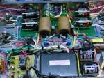
Just wondering why the red/black bias transformer wire on st70 connects to the + side of the selenium rectifier, but - side on a standard diode.
3 posters
Replacing ST70 Selenium Rectifier

Bob Latino- Admin
- Posts : 3276
Join date : 2008-11-26
Location : Massachusetts
The red/black bias wire (the transformers AC bias line) connects to the + side on the selenium rectifier because you are trying to create (on the opposite side of the diode) a NEGATIVE DC voltage. The bias system on Dynaco tube amps runs a negative DC voltage that is "injected" into each octal output tube on pin 5 to control the flow of electrons so that the output tube will be "regulated". If this negative DC voltage is too low or goes to zero then the tube will "red plate" as it "runs away" .. The output tube will usually self destruct if left this way.
An analogy sometimes used to describe bias is that it is similar to walking a baby carriage downhill. Your arms pulling back are like a "bias" to this system as you walk the carriage downhill. If your arms let go ... well I hope there is no baby in the carriage. How steep the hill is, is comparable to the amount of DC voltage in the system. The "hill" would be steeper in a VTA ST-120 which runs a DC voltage of about 500 VDC. The hill would not be as steep in a VTA ST-70 which runs a DC voltage of about 440 to 450 VDC. You have to pull back "harder" (a higher bias) to "rein in" a KT88 in a VTA ST-120 than you do an EL34 in an ST-70.
Bob

rudes- Posts : 63
Join date : 2012-03-07
Thanks Bob, I understand, but I was wondering why the wire connects to the negative side on a modern diode as oppose to the + on the selenium?

arledgsc- Posts : 503
Join date : 2012-11-30
Just wondering why the red/black bias transformer wire on st70 connects to the + side of the selenium rectifier, but - side on a standard diode.
They used electron current flow (- to +) in the "old" days so they had their signal conventions reversed. My first electronics classes involved vacuum tubes and it was all about the negatively charged electrons flow from - to + battery terminal to complete the circuit. Then onto solid state electronics and it was all about "positive hole flow". I tried to understand solid state electronics from the negative electron current perspective but is much easier to understand if you consider current flows positive to negative.
Just think of the side of the rectifier with the more electrons will be more negative than the opposite terminal.


rudes- Posts : 63
Join date : 2012-03-07
OK...Thanks for the explanation!

