The Dynaco Tube Audio Forum

Would you like to react to this message? Create an account in a few clicks or log in to continue.
The Dynaco Tube Audio Forum

Dedicated to the restoration and preservation of all original Dynaco tube audio equipment - Customer support for Tubes4hifi VTA tube amp and preamp kits and all Dynakitparts.com products


+9
Roy Mottram
deepee99
StevieRay
arledgsc
cci1492
audiobill
Peter W.
WLT
bbqjoe
13 posters

    I let the smoke out.

    bbqjoe
    bbqjoe


    Posts : 98
    Join date : 2018-12-03

    I let the smoke out. Empty I let the smoke out.

    Post by bbqjoe Thu Dec 27, 2018 1:13 am

    I finished building my first tube amp yesterday.
    A VTA 120.
    It tested out good, I put in the tubes, turned it on, and Oh my God, the absolute beauty!
    It was beyond words, and only got better as things warmed up.
    I could have cried.

    I took it to the shop this morning (after giving it a six hour test drive yesterday) for a final cleaning.
    I made a change or two as well.
    The slide switch for power doesn't cut it for me, it's not definitive enough, so I installed a toggle.
    I also like having a pilot light, so I found one that was right between red and orange (more orange really) and not too bright.
    I installed that on the front.

    I cleaned up the amp, zip tied it all nicely, took a few pics, closed it up, and carried it into the house.

    I wired up the speakers, plugged it in, flipped on the switch, and 17 seconds later.....ZAP, crackle, Smoke!

    It was right then, I could have really cried.
    My wife was standing right next to me, and she could have cried too.

    I was now just a few milliwatts from tossing almost 3 years of sobriety in the toilet.


    Luckily, Mr Bob is a great guy, we discussed what happened, and I should have what I need to get back up and running in a few days. YAY!
    Fortunately, I don't think the damage is severe.

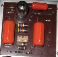
    For the fun of it (if there is any) I'm posting a pic of my build. (First pic)
    I might not have wired it exactly as the pictures, and took a little of my own creative license, but the challenge is to look closely at the (pardon the pun) blown up photo, and see if you can spot where the problem occured right before it happened.

    A virtual 200 bill goes to anyone who spots it in the first pic
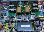
    A virtual 100 bill goes to the one who spots it in the second pic.

    I'll post the carnage after someone spots it.

    I let the smoke out. YRcgECl

    I let the smoke out. 21QGXWi

    WLT
    WLT


    Posts : 187
    Join date : 2013-07-13
    Location : Rochester NY

    I let the smoke out. Empty Re: I let the smoke out.

    Post by WLT Thu Dec 27, 2018 1:40 am

    It looks like your red/black wires that connect to one of the quad cap terminals is very close to the twist lock ground tab. It not possible to see the vertical clearance from the photos but it looks to close to me. The second photo shows your insulation stripped back to a point very near the twist tab.
    bbqjoe
    bbqjoe


    Posts : 98
    Join date : 2018-12-03

    I let the smoke out. Empty Re: I let the smoke out.

    Post by bbqjoe Thu Dec 27, 2018 1:47 am

    WLT wrote:It looks like your red/black wires that connect to one of the quad cap terminals is very close to the twist lock ground tab. It not possible to see the vertical clearance from the photos but it looks to close to me. The second photo shows your insulation stripped back to a point very near the twist tab.

    That's a good point, but I believe there is sufficient clearance there.
    I'll give it consideration before the next flip of the switch.

    But that wasn't it.
    Peter W.
    Peter W.


    Posts : 1351
    Join date : 2016-08-07
    Location : Melrose Park, PA

    I let the smoke out. Empty Re: I let the smoke out.

    Post by Peter W. Thu Dec 27, 2018 7:44 am

    bbqjoe wrote:
    WLT wrote:It looks like your red/black wires that connect to one of the quad cap terminals is very close to the twist lock ground tab. It not possible to see the vertical clearance from the photos but it looks to close to me. The second photo shows your insulation stripped back to a point very near the twist tab.

    That's a good point, but I believe there is sufficient clearance there.
    I'll give it consideration before the next flip of the switch.

    But that wasn't it.

    I don't like two things - the crowd of wiring from/around the choke - but I do not think this was the cause.

    And, the solder-blobs on the rectifier socket - looks like a short waiting to happen.
    avatar
    audiobill


    Posts : 425
    Join date : 2014-03-13
    Location : Albany, NY

    I let the smoke out. Empty Re: I let the smoke out.

    Post by audiobill Thu Dec 27, 2018 8:14 am

    Looks like the resistor and cap cap connected to the quad cap may be touching the chassis, and no solder on that connection.

    You could also consider installing the "yellow sheet diode mod" on the rectifier to protect it.
    cci1492
    cci1492


    Posts : 331
    Join date : 2016-05-09
    Age : 63
    Location : NJ

    I let the smoke out. Empty Re: I let the smoke out.

    Post by cci1492 Thu Dec 27, 2018 11:01 am

    the quad cap connection bill pointed out looks like the problem.
    bbqjoe
    bbqjoe


    Posts : 98
    Join date : 2018-12-03

    I let the smoke out. Empty Re: I let the smoke out.

    Post by bbqjoe Thu Dec 27, 2018 11:33 am

    cci1492 wrote:the quad cap connection bill pointed out looks like the problem.

    That wasn't it, but I'm going to address that one too.

    It's kinda funny to me the things I see in my pics that I didn't see while sitting in front of it.
    arledgsc
    arledgsc


    Posts : 500
    Join date : 2012-11-30
    Age : 70
    Location : Santa Rosa CA

    I let the smoke out. Empty Re: I let the smoke out.

    Post by arledgsc Thu Dec 27, 2018 11:37 am

    Heaters not connected on center tube? At least I don't see the familiar twisted wires from right ch. phase inverter
    bbqjoe
    bbqjoe


    Posts : 98
    Join date : 2018-12-03

    I let the smoke out. Empty Re: I let the smoke out.

    Post by bbqjoe Thu Dec 27, 2018 11:42 am

    arledgsc wrote:Heaters not connected on center tube?  At least I don't see the familiar twisted wires from right ch. phase inverter

    Holy banoonies!
    Looks like I missed something huh?

    Jesus. I'm an idiot.
    arledgsc
    arledgsc


    Posts : 500
    Join date : 2012-11-30
    Age : 70
    Location : Santa Rosa CA

    I let the smoke out. Empty Re: I let the smoke out.

    Post by arledgsc Thu Dec 27, 2018 11:48 am

    Or no solder on rectifier socket pin 6 (HV AC input)?
    arledgsc
    arledgsc


    Posts : 500
    Join date : 2012-11-30
    Age : 70
    Location : Santa Rosa CA

    I let the smoke out. Empty Re: I let the smoke out.

    Post by arledgsc Thu Dec 27, 2018 11:52 am

    Good time to go over each connection and verify parts are installed correctly!
    bbqjoe
    bbqjoe


    Posts : 98
    Join date : 2018-12-03

    I let the smoke out. Empty Re: I let the smoke out.

    Post by bbqjoe Thu Dec 27, 2018 11:59 am

    arledgsc wrote:Good time to go over each connection and verify parts are installed correctly!  

    Indeed.

    Being as it worked, no idea how with a set of wires missing, but I'm pretty sure the parts are in the right place.
    Again, I'm grateful for the pointers you guys are giving out.
    arledgsc
    arledgsc


    Posts : 500
    Join date : 2012-11-30
    Age : 70
    Location : Santa Rosa CA

    I let the smoke out. Empty Re: I let the smoke out.

    Post by arledgsc Thu Dec 27, 2018 12:05 pm

    We can always learn from each issue as we put on our CSI caps to analyze the clues. What actually smoked? What is the problem you spotted?
    bbqjoe
    bbqjoe


    Posts : 98
    Join date : 2018-12-03

    I let the smoke out. Empty Re: I let the smoke out.

    Post by bbqjoe Thu Dec 27, 2018 12:16 pm

    arledgsc wrote:We can always learn from each issue as we put on our CSI caps to analyze the clues.  What actually smoked?  What is the problem you spotted?

    Are we giving up already? Smile
    bbqjoe
    bbqjoe


    Posts : 98
    Join date : 2018-12-03

    I let the smoke out. Empty Re: I let the smoke out.

    Post by bbqjoe Thu Dec 27, 2018 12:30 pm

    arledgsc wrote:Heaters not connected on center tube?  At least I don't see the familiar twisted wires from right ch. phase inverter

    Well since we're here, and I have my pants down...

    I obviously missed the wiring for the heater on the center tube.

    Looking at this next pic, would you also guess I have a heater problem on the left tube as well?

    I let the smoke out. JCER06N
    bbqjoe
    bbqjoe


    Posts : 98
    Join date : 2018-12-03

    I let the smoke out. Empty Re: I let the smoke out.

    Post by bbqjoe Thu Dec 27, 2018 1:08 pm

    After looking at the pic I got with the kit, and the pic on the TFhifi site, there doesn't appear to be a twisted pair called for to the center tube.
    Maybe I'm not such an idiot.

    avatar
    StevieRay


    Posts : 67
    Join date : 2009-01-09
    Age : 61
    Location : Central VA

    I let the smoke out. Empty Re: I let the smoke out.

    Post by StevieRay Thu Dec 27, 2018 1:21 pm

    I just built a VTA ST-120 a month ago -- there are no wires to the center tube heater pins; they're on circuit board traces, even though there are wire connections.

    None were called for in the instructions, and mine work fine.  I then looked and saw the board traces.
    deepee99
    deepee99


    Posts : 2244
    Join date : 2012-05-23
    Location : Wallace, Idaho

    I let the smoke out. Empty Re: I let the smoke out.

    Post by deepee99 Thu Dec 27, 2018 2:27 pm

    17 seconds - hmmmmmmmmmmmm
    Do you have the time-delay relay (TDR) installed? (Not sure but I think that's the little board next to the choke on the RH side of the photos.) You prolly do, given you're using a copper-cap rectum-fryer.
    17 seconds is just about how long it takes for the B+ (high-voltage juice) to enter the circuits giving the filaments time to warm up the tubes first. B+ kicks in, you get smoke.
    So, again, just spit-balling, it' may something to do with weak or nonexistent soldering on a tube socket or chassis-mounted ground lug.
    From your photo, I don't see anything that's missing filament power. All the tubes that should be lit appear to be lit. Ergo, it's not a low-voltage problem. That should narrow your search.
    I'd also take Peter's advice and re-flow the connexions on the rectifier socket. Blobs indicate the lug didn't get hot enough and the solder's all on the wire. Give one a good yank and I bet you'll see movement.


    Roy Mottram
    Roy Mottram
    Admin


    Posts : 1837
    Join date : 2008-11-30

    I let the smoke out. Empty Re: I let the smoke out.

    Post by Roy Mottram Thu Dec 27, 2018 2:36 pm

    I can't see anything in the photos, other than the fact that those K42 PIO caps are not insulated, and thus would work very well as a short circuit conductor for various parts of the circuit board they are on,
    they should have either heat shrink or electrical tape or some sort of insulation between them and the circuit board.
    bbqjoe
    bbqjoe


    Posts : 98
    Join date : 2018-12-03

    I let the smoke out. Empty Re: I let the smoke out.

    Post by bbqjoe Thu Dec 27, 2018 2:48 pm

    deepee99 wrote:17 seconds - hmmmmmmmmmmmm
    Do you have the time-delay relay (TDR) installed? (Not sure but I think that's the little board next to the choke on the RH side of the photos.) You prolly do, given you're using a copper-cap rectum-fryer.
    17 seconds is just about how long it takes for the B+ (high-voltage juice) to enter the circuits giving the filaments time to warm up the tubes first. B+ kicks in, you get smoke.
    So, again, just spit-balling, it' may something to do with weak or nonexistent soldering on a tube socket or chassis-mounted ground lug.
    From your photo, I don't see anything that's missing filament power. All the tubes that should be lit appear to be lit. Ergo, it's not a low-voltage problem. That should narrow your search.
    I'd also take Peter's advice and re-flow the connexions on the rectifier socket. Blobs indicate the lug didn't get hot enough and the solder's all on the wire. Give one a good yank and I bet you'll see movement.


    Yes, 17 seconds, TDR board. Rectifier connections now addressed. 👍


    tubes4hifi wrote: I can't see anything in the photos, other than the fact that those K42 PIO caps are not insulated, and thus would work very well as a short circuit conductor for various parts of the circuit board they are on,
    they should have either heat shrink or electrical tape or some sort of insulation between them and the circuit board.

    I didn't see anything about insulation in the directions, but I see looking closer at the instruction picture, it appears that there is shrink tube on the leads, should I pull the caps then, and shrink tube the leads?

    Thank you guys!
    bbqjoe
    bbqjoe


    Posts : 98
    Join date : 2018-12-03

    I let the smoke out. Empty Re: I let the smoke out.

    Post by bbqjoe Thu Dec 27, 2018 5:29 pm

    I've now gone back and cleaned up a bunch of stuff that I can't believe I wasn't unhappy with.
    Must have just been excitement and enthusiasm clouding my eyesight.

    I replaced a handful of wires, redid some connections, and reflowed some joints.
    I realize now that I left way too much of an insulation gap on quite a few joints, they have also been fixed.
    I paid particular attention to anything that was close to anything else.
    Just don't want any more shorts, thank you!

    Anyways, here's where my problem was.
    I broke the wire going to the switch while tying everything up.
    It arced between the switch and the resistor.
    Resistor was fried, not to mention the switch.

    I let the smoke out. Hy0l6VF

    I let the smoke out. DGaGv8L
    bbqjoe
    bbqjoe


    Posts : 98
    Join date : 2018-12-03

    I let the smoke out. Empty Re: I let the smoke out.

    Post by bbqjoe Tue Jan 01, 2019 12:53 am

    Well, I'm back in action!
    Bob to the rescue.
    He sent a new switch, a few resistors, and some fuses 2 day mail.
    Of course to the postal folks that means 5.

    But this gave me some time to relax and think about things.
    I thought I was going slow and easy, but obviously not slow and easy enough. (Tough, but not awful lesson)

    I sat down and spent a number of hours correcting things that I should never have accepted from myself.
    I replaced some wire, rerouted some, and redid a handful of unacceptable joints.

    I would happily build another one of these, and the experience I got would make the next one look even better now understanding the where and why of things.

    I'm a happy camper, and the ST-120 makes my Dahlquist's sound wonderful!

    I just purchased two pairs of Wharfedale's. One set is W60E's and the other set is missing it's model number, but it appears to be a two way, as compared to a three.
    I have yet to drive to Phoenix and pick them up, but I'm betting after getting them and most likely recapping them, I'll be in heaven.
    I love the sound from this amp. Thanks Bob for all your help.

    I let the smoke out. BWIatY3


    I let the smoke out. JCER06N
    deepee99
    deepee99


    Posts : 2244
    Join date : 2012-05-23
    Location : Wallace, Idaho

    I let the smoke out. Empty Re: I let the smoke out.

    Post by deepee99 Tue Jan 01, 2019 2:06 pm

    BBQJoe,
    Looks a lot better. I had the same sort of time for reflection on my M-125 builds whilst waiting for Bob L. to send me a new tube socket to replace the one I'd ruined, and the intervening days gave me time to re-do, re-route and re-solder some wiring as well.
    Not to be picky, and it could just be the lighting, but I still don't see any insulation on the leads on those big PIO caps. As Roy mentioned earlier, insulating them is a must for a lot of reasons.
    If that be the case, rather than going through the hassle of de-soldering them to slide insulation tubing over them, then re-soldering them, try some liquid insulation, comes in a little can, and literally paint the insulation onto them in situ. For example, this stuff:
    https://www.usplastic.com/catalog/item.aspx?sku=38086&gclid=EAIaIQobChMIrJLK3pTN3wIVAihpCh0TKQP1EAQYAyABEgKjkvD_BwE
    If the brush on the can-lid is too big to get in there, a fingernail polish brush works just ducky.
    Cheerio,
    deepee
    P.S. I had a pair of DQ-10s and sure enjoyed them with a Carver s/s set-up. They were, maybe still are, like Magnepan, a friendly, family-run company.
    bbqjoe
    bbqjoe


    Posts : 98
    Join date : 2018-12-03

    I let the smoke out. Empty Re: I let the smoke out.

    Post by bbqjoe Tue Jan 01, 2019 2:14 pm

    deepee99 wrote:BBQJoe,
    Looks a lot better. I had the same sort of time for reflection on my M-125 builds whilst waiting for Bob L. to send me a new tube socket to replace the one I'd ruined, and the intervening days gave me time to re-do, re-route and re-solder some wiring as well.
    Not to be picky, and it could just be the lighting, but I still don't see any insulation on the leads on those big PIO caps. As Roy mentioned earlier, insulating them is a must for a lot of reasons.
    If that be the case, rather than going through the hassle of de-soldering them to slide insulation tubing over them, then re-soldering them, try some liquid insulation, comes in a little can, and literally paint the insulation onto them in situ. For example, this stuff:
    https://www.usplastic.com/catalog/item.aspx?sku=38086&gclid=EAIaIQobChMIrJLK3pTN3wIVAihpCh0TKQP1EAQYAyABEgKjkvD_BwE
    If the brush on the can-lid is too big to get in there, a fingernail polish brush works just ducky.
    Cheerio,
    deepee

    The caps are mounted off the board per Bob's instructions. Somewhere between 1/8 and 1/4 inch.
    I spoke with Bob, and he verified that this is all that was needed.
    I went ahead anyway and put a few layers of electrical tape below the caps just for even more piece of mind.
    Once again, insulating the legs was not in the instructions, otherwise I would have done it. I have shrink tubing on hand.

    I appreciate your concern. I hate smoke and crackle. Wink
    avatar
    audiobill


    Posts : 425
    Join date : 2014-03-13
    Location : Albany, NY

    I let the smoke out. Empty Re: I let the smoke out.

    Post by audiobill Tue Jan 01, 2019 5:41 pm

    You don't need insulation on legs....

    Sponsored content


    I let the smoke out. Empty Re: I let the smoke out.

    Post by Sponsored content


      Current date/time is Sun May 19, 2024 3:14 am