The Dynaco Tube Audio Forum

Would you like to react to this message? Create an account in a few clicks or log in to continue.
The Dynaco Tube Audio Forum

Dedicated to the restoration and preservation of all original Dynaco tube audio equipment - Customer support for Tubes4hifi VTA tube amp and preamp kits and all Dynakitparts.com products


4 posters

    Adding an internal tube buffer to the PH12

    avatar
    rjpjnk


    Posts : 262
    Join date : 2018-07-18

    Adding an internal tube buffer to the PH12 Empty Adding an internal tube buffer to the PH12

    Post by rjpjnk Tue Jun 11, 2019 4:55 pm

    I have a PH12/SP12 combo and all the talk recently about buffered phono stages has got me thinking it would be nice to have. Then I could potentially use the tape loop if I wanted to.

    The neatest solution would be to buy a PH14 to replace the PH12, but I looked at the PH14 board but it appears too big to fit in my 12"x12"x4" chassis where my PH12 & SP12 is now.

    I wonder if I could build a tiny little 2" board with a single tube cathode follower? I already have the B+ and filament supply, so I would only need a few resistors and caps and a tube socket, right?

    Roy: Do you have a little buffer board like this available? I bet there are a number of us PH10/PH12 owners out there that would buy one. If not, do you know of a prefab board that would do the trick? Homemade breadboard would be my last option, in which case all I need is a good schematic recommendation.

    No hurry, just thinking about the next project for a rainy day. I am already planning the transformer upgrade we discussed previously in order to give the regulators more power to work with.

    Appreciate any inputs, or just interesting discussion. Thanks!
    avatar
    Guest
    Guest


    Adding an internal tube buffer to the PH12 Empty Re: Adding an internal tube buffer to the PH12

    Post by Guest Tue Jun 11, 2019 7:29 pm

    do a 'tube buffer kit' search on Google, and you'll get quite a few options available, that may be your best bet.
    avatar
    rjpjnk


    Posts : 262
    Join date : 2018-07-18

    Adding an internal tube buffer to the PH12 Empty Re: Adding an internal tube buffer to the PH12

    Post by rjpjnk Wed Jun 12, 2019 11:27 am

    Thanks. I did find some little Chinese Ebay boards without power supplies when searching for "small tube buffer circuit board", but I'm not sure I trust these designs. And I don't know if they would integrate well with the PH12 output.

    So in the spirit of learning something new I did a little reading and found tons of info on cathode followers. It seems the most basic circuits use just 3 or 4 resistors and 2 capacitors per channel, and common tube choices are 12au7, 12AX7, 6DT8, 6SN7, among others. I like the idea of a single twin triode handling both channels. I am attracted to the 12au7/12ax7 since I have a lot of them.

    If anyone has a favorite design using one of these tubes I would appreciate it.

    I found the following link very interesting, but it may be over complicating things for my needs. It points out a lot of potential pitfalls in design, and quickly moves on to designs using two triodes per channel (White Cathode Follower). I was hoping to stick to a single tube design.
    http://www.tubecad.com/october99/index.html


    peterh
    peterh


    Posts : 1869
    Join date : 2012-12-25
    Location : gothenburg, sweden

    Adding an internal tube buffer to the PH12 Empty Re: Adding an internal tube buffer to the PH12

    Post by peterh Wed Jun 12, 2019 2:17 pm

    rjpjnk wrote:Thanks. I did find some little Chinese Ebay boards without power supplies when searching for "small tube buffer circuit board", but I'm not sure I trust these designs. And I don't know if they would integrate well with the PH12 output.

    So in the spirit of learning something new I did a little reading and found tons of info on cathode followers. It seems the most basic circuits use just 3 or 4 resistors and 2 capacitors per channel, and common tube choices are 12au7, 12AX7, 6DT8,  6SN7, among others. I like the idea of a single twin triode handling both channels. I am attracted to the 12au7/12ax7 since I have a lot of them.

    If anyone has a favorite design using one of these tubes I would appreciate it.

    I found the following link very interesting, but it may be over complicating things for my needs. It points out a lot of potential pitfalls in design, and quickly moves on to designs using two triodes per channel (White Cathode Follower). I was hoping to stick to a single tube design.
    http://www.tubecad.com/october99/index.html


    A good introduction is at merlin blencove's site : http://www.valvewizard.co.uk/accf.html

    In addition i tested a FET-based buffer intended to be mounted inside a PAS, getting the
    minuscule power needed from the filament power.  It's still mounted in a PAS !
    ( similar : https://www.ebay.com/itm/Dynaco-PAS-Preamp-Impedance-Matching-Module-New/303180358355?hash=item4696f522d3:g:2aIAAOSwTm9c-X5E )
    I decoded the schematics, and it's really nothing special. But it works and according to my ears
    it has no negative drawback. As i reverse engineered this i consider this MY work and feel
    free to share on request.

    Cheaper fet buffers are available at ebay.( but many has push-pull , not class A types) I think that
    a buffer should be minimalistic, using only one class-A device and a corresponding resistor.


    Last edited by peterh on Wed Jun 12, 2019 3:28 pm; edited 1 time in total (Reason for editing : Spelling)
    avatar
    rjpjnk


    Posts : 262
    Join date : 2018-07-18

    Adding an internal tube buffer to the PH12 Empty Re: Adding an internal tube buffer to the PH12

    Post by rjpjnk Wed Jun 12, 2019 8:22 pm

    Peter, I remember that FET buffer. I built a similar one for my PAS back then as well. It is a great choice when there is no power to spare from the transformer for sure.

    I want to try a tube buffer this time.

    Thanks for the link.
    Roy Mottram
    Roy Mottram
    Admin


    Posts : 1839
    Join date : 2008-11-30

    Adding an internal tube buffer to the PH12 Empty Re: Adding an internal tube buffer to the PH12

    Post by Roy Mottram Sat Jun 15, 2019 2:16 pm

    https://www.ebay.com/itm/TR2-6DJ8-ECC88-E88CC-Tube-Buffer-Pre-amplifier-Preamp-For-DAC-CD-Player-Audio/253615257235?

    $8

    or you can breadboard the PH14 output buffer, probably cost you more than twice as much for the parts
    avatar
    rjpjnk


    Posts : 262
    Join date : 2018-07-18

    Adding an internal tube buffer to the PH12 Empty Re: Adding an internal tube buffer to the PH12

    Post by rjpjnk Sat Jun 15, 2019 9:42 pm

    That is a neat little board Roy, but it requires +-24VDC for the B+. Not sure how I would derive that from the voltages in the SP12.
    peterh
    peterh


    Posts : 1869
    Join date : 2012-12-25
    Location : gothenburg, sweden

    Adding an internal tube buffer to the PH12 Empty Re: Adding an internal tube buffer to the PH12

    Post by peterh Sun Jun 16, 2019 1:05 am

    tubes4hifi wrote:https://www.ebay.com/itm/TR2-6DJ8-ECC88-E88CC-Tube-Buffer-Pre-amplifier-Preamp-For-DAC-CD-Player-Audio/253615257235?

    $8

    or you can breadboard the PH14 output buffer, probably cost you more than twice as much for the parts

    A pity that something that could be a good buffer is deliberatly designed to run the tube well
    below optimum voltage. And if thought to be installed in a tubeamp where proper B+ is
    present.

    Maybe the amp could be redesigned ( resistor changes ?) for proper B+ ? Is there
    a schematics available ?
    avatar
    rjpjnk


    Posts : 262
    Join date : 2018-07-18

    Adding an internal tube buffer to the PH12 Empty Re: Adding an internal tube buffer to the PH12

    Post by rjpjnk Sun Jun 16, 2019 11:19 pm

    peterh wrote:
    tubes4hifi wrote:https://www.ebay.com/itm/TR2-6DJ8-ECC88-E88CC-Tube-Buffer-Pre-amplifier-Preamp-For-DAC-CD-Player-Audio/253615257235?

    $8

    or you can breadboard the PH14 output buffer, probably cost you more than twice as much for the parts

    A pity that something that could be a good buffer is deliberatly designed to run the tube well
    below optimum voltage. And if thought to be installed in a tubeamp where proper B+ is
    present.

    Maybe the amp could be redesigned ( resistor changes ?) for proper B+ ? Is there
    a schematics available ?

    I'm sure it could be redesigned. I found what appears to be the bare board here and it includes a schematic.
    https://www.ebay.com/itm/Mini-Tube-Amp-Buffer-Circuit-Board-PCB-Bile-Taste-Fit-for-6DJ8-12AU7-Car-audio/112964311060

    I am thinking of using this board to build the PH14 buffer circuit because it would look neater than breadboard. The schematic does not show a grid stopper resistor unfortunately, but looking at the pics it looks pretty easy to add this resistor. Fortunately the 12au7 has the same pinout as the 6DJ8 the board calls for. For 5 bucks it's worth a shot.
    peterh
    peterh


    Posts : 1869
    Join date : 2012-12-25
    Location : gothenburg, sweden

    Adding an internal tube buffer to the PH12 Empty Re: Adding an internal tube buffer to the PH12

    Post by peterh Mon Jun 17, 2019 4:04 am

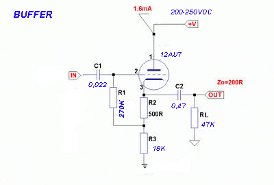
    Regarding the buffer board; yes the values of the schematics are off by one or two digits !
    Input cap 1uF ??? When 0.022 would do just fine. R1 here would 270k be fine and allow a more
    stable operation. Feeding it from -25 to +25 is not needed, ground R3 instead of -25, increase to 18k
    C2 may be 0.47uF and use 47k for RL. With these changes a normal B+ in the range of
    200 - 250V would be fine.

    The important is that a small board buffering 2 channels are available.
    Roy Mottram
    Roy Mottram
    Admin


    Posts : 1839
    Join date : 2008-11-30

    Adding an internal tube buffer to the PH12 Empty Re: Adding an internal tube buffer to the PH12

    Post by Roy Mottram Mon Jun 17, 2019 2:28 pm

    perfect PCB, yes, and I agree with the value changes Peter made
    Pillo69
    Pillo69


    Posts : 176
    Join date : 2012-04-11
    Location : Granada (España)

    Adding an internal tube buffer to the PH12 Empty Re: Adding an internal tube buffer to the PH12

    Post by Pillo69 Mon Jun 17, 2019 4:11 pm

    peterh wrote:Regarding the buffer board; yes the values of the schematics are off by one or two digits !
    Input cap 1uF ??? When 0.022 would do just fine. R1 here would 270k be fine and allow a more
    stable operation.  Feeding it from -25 to +25 is not needed, ground R3 instead of -25, increase to 18k
    C2 may be 0.47uF and use 47k for RL. With these changes a normal B+ in the range of
    200 - 250V would be fine.

    The important is that a small board buffering 2 channels are available.

    Adding an internal tube buffer to the PH12 Buffer-seguidor-de-catodo
    avatar
    rjpjnk


    Posts : 262
    Join date : 2018-07-18

    Adding an internal tube buffer to the PH12 Empty Re: Adding an internal tube buffer to the PH12

    Post by rjpjnk Wed Jun 19, 2019 10:53 am

    peterh wrote:Regarding the buffer board; yes the values of the schematics are off by one or two digits !
    Input cap 1uF ??? When 0.022 would do just fine. R1 here would 270k be fine and allow a more
    stable operation.  Feeding it from -25 to +25 is not needed, ground R3 instead of -25, increase to 18k
    C2 may be 0.47uF and use 47k for RL. With these changes a normal B+ in the range of
    200 - 250V would be fine.

    The important is that a small board buffering 2 channels are available.

    Yes! It is just what I was looking for.

    Would you not add a grid stopper resistor? I see them in many other CF schematics, though not sure they are really necessary.

    http://www.valvewizard.co.uk/accf.html
    peterh
    peterh


    Posts : 1869
    Join date : 2012-12-25
    Location : gothenburg, sweden

    Adding an internal tube buffer to the PH12 Empty Re: Adding an internal tube buffer to the PH12

    Post by peterh Wed Jun 19, 2019 12:41 pm

    rjpjnk wrote:
    peterh wrote:Regarding the buffer board; yes the values of the schematics are off by one or two digits !
    Input cap 1uF ??? When 0.022 would do just fine. R1 here would 270k be fine and allow a more
    stable operation.  Feeding it from -25 to +25 is not needed, ground R3 instead of -25, increase to 18k
    C2 may be 0.47uF and use 47k for RL. With these changes a normal B+ in the range of
    200 - 250V would be fine.

    The important is that a small board buffering 2 channels are available.

    Yes! It is just what I was looking for.

    Would you not add a grid stopper resistor? I see them in many other CF schematics, though not sure they are really necessary.

    http://www.valvewizard.co.uk/accf.html

    You _should_ add a grid stopper BUT ; you might need to cut the traces close to pin 2 and 7
    and add your grid stopper across the cut.

    The board is not perfect ( components on underside etc ) but lacking alternative it could
    with some work be useful.

    Sponsored content


    Adding an internal tube buffer to the PH12 Empty Re: Adding an internal tube buffer to the PH12

    Post by Sponsored content


      Current date/time is Fri Nov 22, 2024 7:47 am