The Dynaco Tube Audio Forum

Would you like to react to this message? Create an account in a few clicks or log in to continue.
The Dynaco Tube Audio Forum

Dedicated to the restoration and preservation of all original Dynaco tube audio equipment - Customer support for Tubes4hifi VTA tube amp and preamp kits and all Dynakitparts.com products


+12
CletusB
Ernstmach
Roy Mottram
corndog71
pavlikkkk
markeby
Bob Latino
Peter W.
pichacker
HarryY
LeGrace
cci1492
16 posters

    Pavel's Auto-Bias Board

    Peter W.
    Peter W.


    Posts : 1351
    Join date : 2016-08-07
    Location : Melrose Park, PA

    Pavel's Auto-Bias Board Empty Pavel's Auto-Bias Board

    Post by Peter W. Thu Aug 01, 2019 10:21 am

    Long story, of which I will summarize. A gentleman from this venue asked me to install the latest "isolated" AB board in his Latino-assembled 120. Given my general opinion on the process, I felt that I owed it to myself to get a hands-on experience with both items. So, here goes:

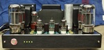
    a) The ST120 is truly an elegant piece of tube-gear.
    b) The assembly was flawless, the parts quality, spacing, and general layout clean and easy to understand.
    c) The AB board was also an elegant piece of kit, using a good quality board, nicely masked and with through-plated soldering pads.

    So, based on first-impressions, I looked forward to a relatively simple install. No such luck.

    I keep a very nice bench AC power-supply, so pre-biasing the board was direct and simple.
    Pavel advises that the VTA board be removed for installation. Simply not practical when the Volume Control is installed. It would require undoing much of Bob's handiwork and greatly multiply occasions for error.
    The two tall caps on the VTA board must be replaced with short caps for clearance. Given that those caps terminate under the chassis, getting to them required my flexible soldering iron (not really), which I managed with great caution, super good light and care.
    It took two (2) passes with Pavel to get the correct installation instructions. Had I followed what I was given both by the amp owner and from Pavel the first time... well...
    HOWEVER, once the correct instructions arrived, it was an easy finish.
    At which point, the board performed as-planned and as-advertised.

    Now, the quibbles:

    Directions. I believe that path is now cleared up, and new boards will have new directions, which will be easily followed and give good results.
    Hardware supplied: Missing screws. Two stand-offs per leg, should be one.
    Board does not clear the Volume control, and so that corner, and the one one the other side cannot be tightened down. I used the original KEP nut, my own 4-40 stainless steel screws (not going to pollute with mild steel) and tiny wrenches to secure the two corners against 'wiggle'.
    Owner wanted me to drill the VTA board to expose the LEDs for visual verification. The PIO caps prevented that option. Pavel was good enough to supply that board without the SMT LEDs, but to no avail. I mounted conventional Blue LEDs on the back - they light, but are invisible. Perhaps a fiber-optic cable might be an option.
    The soldering techniques required by the install, to me, verge on the dangerous - I have very nearly 50 years experience with soldering, so, I used that experience to make the best of difficult choices. Funny thing, if Bob Latino were a sloppier technician, it would have been easier. BUT!! I repeat, those who do not have absolute confidence in their technique should get help on this part of the install.

    Conclusions:

    Whereas the board is functional and meets the need and the goal, it should be physically modified to accommodate the volume control. Were an ALPS type control installed - there would have been no way to install it.
    Pavel and Bob should work out something so that some of the key soldering points on the VTA board were accommodated, rather than double-connecting and relying solely on the strength of the solder to maintain the connection. I use good, fresh 63/37 Eutectic Solder from a top source, but it still leaves me feeling squirrelly.

    Nor would I install such a device on my personal equipment. I like the (or tell myself I like) the hands-on maintenance aspect of biasing. That is a personal prejudice, not a criticism.

    This was an excellent learning experience, and well worth the price of admission - had all things been aligned from the beginning, start-to-finish, it would have been a 3-hour ordeal as I am a measure-twice/cut-once type, measure-3x on some one else's gear.

    cci1492
    cci1492


    Posts : 331
    Join date : 2016-05-09
    Age : 63
    Location : NJ

    Pavel's Auto-Bias Board Empty Re: Pavel's Auto-Bias Board

    Post by cci1492 Thu Aug 01, 2019 11:50 am

    Good to know, any photos? Thanks.


    Last edited by cci1492 on Thu Aug 01, 2019 4:30 pm; edited 1 time in total
    avatar
    Guest
    Guest


    Pavel's Auto-Bias Board Empty Re: Pavel's Auto-Bias Board

    Post by Guest Thu Aug 01, 2019 3:02 pm

    yes, please provide photo's of the completed install, so that any possible mods to the pcb can perhaps be carried out. Once these photo's are handy, I will go over it with Pavel.
    Apologies for missing the hardware, that would have been my bad.
    I agree with the part regarding additional solder pads to accommodate the wiring for the AB module, for both the noval & octal ST70/120 pcb's as well as the M125 pcb's. It is not a big deal to modify the pcb layout to add these extra solder pads and could be easily implemented/added with the next order batch of the above mentioned pcb's.
    I guess the ball is now in Bob's and Roy's court.
    LeGrace
    LeGrace


    Posts : 390
    Join date : 2016-08-07
    Location : Ontario, Canada

    Pavel's Auto-Bias Board Empty Re: Pavel's Auto-Bias Board

    Post by LeGrace Fri Aug 02, 2019 11:08 am

    I am in the process of adding AB`s to my M125`s. A process that so far has not quite gone according to plan. A few minutes after the blue leds came on I heard a sizzle sound and smoke started pouring from a cap on the M125 driver board. Now everything has to come back out so I can assess extent of damage and make repairs, which in turn necessitates starting all over again.

    Aftersales support from erhard-audio has been excellent They got back to me quickly and after many emails back and forth I am ready to have another go and am not feeling as lost anymore. I cannot blame the kit in any way, clear case of human error stemming from inadequate skill level.  Embarassed

    Of Peter`s comments this one resonates most loudly:

    "The soldering techniques required by the install, to me, verge on the dangerous - I have very nearly 50 years experience with soldering, so, I used that experience to make the best of difficult choices. Funny thing, if Bob Latino were a sloppier technician, it would have been easier. BUT!! I repeat, those who do not have absolute confidence in their technique should get help on this part of the install."

    Because this is exactly where things went off the rails for me. One joint in particular I really struggled with. I ended up making a mess of it and this of course is where the failure originates. Funny thing as I was working on it the thought crossed my mind that this would be a whole lot easier if I had a fresh cap with untrimmed leads on hand. All this grief for the sake of a part costing under 2 bucks, but I was unwilling to wait the extra couple days it would take to get one. Now I sure wish I had followed up on that thought!!

    My post is not meant to discourage anyone, just a cautionary tale. The kit quality and instructions are all excellent. Plus if you do get into trouble as I said folks are on hand to help. One other piece of advice do yourself a big favor by using twisted wire versus solid core. You want to be using the most flexible wiring possible for this upgrade. Will save a lot of hassle, trust me.

    I will report back after round 2.
    Peter W.
    Peter W.


    Posts : 1351
    Join date : 2016-08-07
    Location : Melrose Park, PA

    Pavel's Auto-Bias Board Empty Re: Pavel's Auto-Bias Board

    Post by Peter W. Mon Aug 05, 2019 8:49 am

    https://www.dropbox.com/sh/bycbdfgjpgat4do/AAD8xMTAlLuOlLjB7bFavzYEa?dl=0

    Pictures.

    Correction: The Owner of the amp did the assembly. Super-neat work! I was fooled by Bob Latino's signature.
    HarryY
    HarryY


    Posts : 46
    Join date : 2019-07-24
    Location : NY

    Pavel's Auto-Bias Board Empty Re: Pavel's Auto-Bias Board

    Post by HarryY Mon Aug 05, 2019 2:31 pm

    The Auto-Bias Boards need to have a header for each
    of the LEDs so that they can be mounted remotely.


    I nearly ordered one but once I realized I'd have to unsolder
    the surface mount LED and tack on a header so I could put
    the LEDs somewhere I could see them I decided against it.

    It didn't make sense to have an indicator LED inside
    the amplifier chassis case where I could not see it.

    .
    Peter W.
    Peter W.


    Posts : 1351
    Join date : 2016-08-07
    Location : Melrose Park, PA

    Pavel's Auto-Bias Board Empty Re: Pavel's Auto-Bias Board

    Post by Peter W. Mon Aug 05, 2019 2:50 pm

    HarryY wrote:

    It didn't make sense to have an indicator LED inside
    the amplifier chassis case where I could not see it.

    .

    As I understand it, the purpose of the LEDs is to indicate that the board is working at the initial set-up. After which, in the proper Brooklyn accent - fuggedaboutit!  

    Pavel calls for this initial test to be either with speakers, or a dummy load and shorting plugs on the inputs. I made a couple of dummy-loads and two shorting-plugs for the owner to take home. All that fits in a pocket, much easier than managing speakers.

    https://semispares.com/wp-content/uploads/2019/07/cf948891603fbcc06c6f0237d0d2b56e.jpg  

    Given that the amp is not actually passing signal, a 50-watt fixed resistor (one per channel), anywhere from 4 - 16 ohms is fine for that test. I have a box full of NIB 5-ohm devices I rescued from a dumpster...
    avatar
    Guest
    Guest


    Pavel's Auto-Bias Board Empty Re: Pavel's Auto-Bias Board

    Post by Guest Mon Aug 05, 2019 2:50 pm

    HarryY wrote:The Auto-Bias Boards need to have a header for each
    of the LEDs so that they can be mounted remotely.


    I nearly ordered one but once I realized I'd have to unsolder
    the surface mount LED and tack on a header so I could put
    the LEDs somewhere I could see them I decided against it.

    It didn't make sense to have an indicator LED inside
    the amplifier chassis case where I could not see it.

    .

    the new versions of the AB modules have holes in the surface mount pads where the factory blue LED's are mounted on to. Removing the surface mount LED's is not at all difficult, which then leaves a pad with a through hole to fit a 24gauge wire through it.
    Either solder wick or a vacuum solder sucker will expose the small through hole on those pads.
    The AB modules are a universal design for use with pretty much any tube amp which uses manual bias adjustment, then two pcb styles were adapted to use in the Dynaco ST70, or the new generation ST120 and M125 chassis'.

    It makes more sense to supply a 'complete' AB module without any loose LED's if headers were used. Then there is the question of do we supply the AB module with LED headers with wires already hooked up to the LED's with a female header at the other end, then how long should those wires be, as each amp is different requiring custom wire length for the external LED's.
    Then there is always the possibility of a user installing the LED the wrong way around, polarity wise, even with some kind of polarity indication.
    That is why it makes more sense to supply the AB module with the surface mount LED's, then the user can decide on remote LED's or not.
    Most installations do not use remote LED's, this is up to the individual user to decide.
    HarryY
    HarryY


    Posts : 46
    Join date : 2019-07-24
    Location : NY

    Pavel's Auto-Bias Board Empty Re: Pavel's Auto-Bias Board

    Post by HarryY Mon Aug 05, 2019 3:14 pm

    erhard-audio wrote:
    HarryY wrote:The Auto-Bias Boards need to have a header for each
    of the LEDs so that they can be mounted remotely.


    I nearly ordered one but once I realized I'd have to unsolder
    the surface mount LED and tack on a header so I could put
    the LEDs somewhere I could see them I decided against it.

    It didn't make sense to have an indicator LED inside
    the amplifier chassis case where I could not see it.

    .

    the new versions of the AB modules have holes in the surface mount pads where the factory blue LED's are mounted on to. Removing the surface mount LED's is not at all difficult, which then leaves a pad with a through hole to fit a 24gauge wire through it.
    Either solder wick or a vacuum solder sucker will expose the small through hole on those pads.
    The AB modules are a universal design for use with pretty much any tube amp which uses manual bias adjustment, then two pcb styles were adapted to use in the Dynaco ST70, or the new generation ST120 and M125 chassis'.

    It makes more sense to supply a 'complete' AB module without any loose LED's if headers were used. Then there is the question of do we supply the AB module with LED headers with wires already hooked up to the LED's with a female header at the other end, then how long should those wires be, as each amp is different requiring custom wire length for the external LED's.
    Then there is always the possibility of a user installing the LED the wrong way around, polarity wise, even with some kind of polarity indication.
    That is why it makes more sense to supply the AB module with the surface mount LED's, then the user can decide on remote LED's or not.
    Most installations do not use remote LED's, this is up to the individual user to decide.


    Will the new board clear the Stepped Attenuator / Volume control on the ST-120 amplifier?


    avatar
    Guest
    Guest


    Pavel's Auto-Bias Board Empty Re: Pavel's Auto-Bias Board

    Post by Guest Mon Aug 05, 2019 3:27 pm

    HarryY wrote:
    erhard-audio wrote:
    HarryY wrote:The Auto-Bias Boards need to have a header for each
    of the LEDs so that they can be mounted remotely.


    I nearly ordered one but once I realized I'd have to unsolder
    the surface mount LED and tack on a header so I could put
    the LEDs somewhere I could see them I decided against it.

    It didn't make sense to have an indicator LED inside
    the amplifier chassis case where I could not see it.

    .

    the new versions of the AB modules have holes in the surface mount pads where the factory blue LED's are mounted on to. Removing the surface mount LED's is not at all difficult, which then leaves a pad with a through hole to fit a 24gauge wire through it.
    Either solder wick or a vacuum solder sucker will expose the small through hole on those pads.
    The AB modules are a universal design for use with pretty much any tube amp which uses manual bias adjustment, then two pcb styles were adapted to use in the Dynaco ST70, or the new generation ST120 and M125 chassis'.

    It makes more sense to supply a 'complete' AB module without any loose LED's if headers were used. Then there is the question of do we supply the AB module with LED headers with wires already hooked up to the LED's with a female header at the other end, then how long should those wires be, as each amp is different requiring custom wire length for the external LED's.
    Then there is always the possibility of a user installing the LED the wrong way around, polarity wise, even with some kind of polarity indication.
    That is why it makes more sense to supply the AB module with the surface mount LED's, then the user can decide on remote LED's or not.
    Most installations do not use remote LED's, this is up to the individual user to decide.


    Will the new board clear the Stepped Attenuator / Volume control on the ST-120 amplifier?


    that cutout has not been changed since the custom pcb for the AB module was first created by Roy of Tubes4HiFi some time back. We can only assume that Roy took all those parts, their size and location into account when the custom AB pcb was created. But, as it may seem, there could be some issues, so perhaps Roy could chime in here.
    HarryY
    HarryY


    Posts : 46
    Join date : 2019-07-24
    Location : NY

    Pavel's Auto-Bias Board Empty Re: Pavel's Auto-Bias Board

    Post by HarryY Mon Aug 05, 2019 11:17 pm

    erhard-audio wrote:
    HarryY wrote:
    erhard-audio wrote:
    HarryY wrote:The Auto-Bias Boards need to have a header for each
    of the LEDs so that they can be mounted remotely.


    I nearly ordered one but once I realized I'd have to unsolder
    the surface mount LED and tack on a header so I could put
    the LEDs somewhere I could see them I decided against it.

    It didn't make sense to have an indicator LED inside
    the amplifier chassis case where I could not see it.

    .

    the new versions of the AB modules have holes in the surface mount pads where the factory blue LED's are mounted on to. Removing the surface mount LED's is not at all difficult, which then leaves a pad with a through hole to fit a 24gauge wire through it.
    Either solder wick or a vacuum solder sucker will expose the small through hole on those pads.
    The AB modules are a universal design for use with pretty much any tube amp which uses manual bias adjustment, then two pcb styles were adapted to use in the Dynaco ST70, or the new generation ST120 and M125 chassis'.

    It makes more sense to supply a 'complete' AB module without any loose LED's if headers were used. Then there is the question of do we supply the AB module with LED headers with wires already hooked up to the LED's with a female header at the other end, then how long should those wires be, as each amp is different requiring custom wire length for the external LED's.
    Then there is always the possibility of a user installing the LED the wrong way around, polarity wise, even with some kind of polarity indication.
    That is why it makes more sense to supply the AB module with the surface mount LED's, then the user can decide on remote LED's or not.
    Most installations do not use remote LED's, this is up to the individual user to decide.


    Will the new board clear the Stepped Attenuator / Volume control on the ST-120 amplifier?


    that cutout has not been changed since the custom pcb for the AB module was first created by Roy of Tubes4HiFi some time back. We can only assume that Roy took all those parts, their size and location into account when the custom AB pcb was created. But, as it may seem, there could be some issues, so perhaps Roy could chime in here.

    Thank you

    I may need to revisit my thoughts on auto bias.


    avatar
    Guest
    Guest


    Pavel's Auto-Bias Board Empty Re: Pavel's Auto-Bias Board

    Post by Guest Mon Aug 05, 2019 11:40 pm

    the auto bias module works, and works well, period.
    It may not be to everyones preference to use an auto bias system and that is of course the choice we all have.
    pichacker
    pichacker


    Posts : 103
    Join date : 2016-08-01
    Age : 59
    Location : Near to London - UK

    Pavel's Auto-Bias Board Empty Re: Pavel's Auto-Bias Board

    Post by pichacker Tue Aug 06, 2019 2:53 am

    I'm with Erhard on this one. The board does everything it says on the box and more!!

    Admittedly I don't have the stepped attenuator but the fitting of the board went without any major issues apart from having to lay down my caps for the bias supply as they were of the tall variety.

    Comments re soldering to small pads above not an issue. Anyone with any soldering skills can do this without risk, and why would anyone want to move the LED's? If you look at the circuit they aren't just indicators but provide a fixed voltage drop to allow the output stage of the AB to operate in constant current mode. If the LED is open circuited then the conditions in the circuit will be affected, not in a good way. Best to leave them on the board i'd say......
    Peter W.
    Peter W.


    Posts : 1351
    Join date : 2016-08-07
    Location : Melrose Park, PA

    Pavel's Auto-Bias Board Empty Re: Pavel's Auto-Bias Board

    Post by Peter W. Tue Aug 06, 2019 7:17 am

    pichacker wrote:I'm with Erhard on this one. The board does everything it says on the box and more!!

    Admittedly I don't have the stepped attenuator but the fitting of the board went without any major issues apart from having to lay down my caps for the bias supply as they were of the tall variety.

    Comments re soldering to small pads above not an issue. Anyone with any soldering skills can do this without risk, and why would anyone want to move the LED's? If you look at the circuit they aren't just indicators but provide a fixed voltage drop to allow the output stage of the AB to operate in constant current mode. If the LED is open circuited then the conditions in the circuit will be affected, not in a good way. Best to leave them on the board i'd say......

    "Instead of blue LEDs there can be any other LEDs. Neither Uf nor If
    these LEDs matter, nor color.
    The LED cathodes are oriented towards the center of the AB plate. The
    LED anodes are facing the BRD and CATH pins."


    The above is from Pavel, when I asked if the forward bias of the LED made any difference. Apparently, it does not.
    This is not to suggest that the fact that an LED is in place does not affect the circuit overall, but it would appear that it is not very critical as to the nature of that LED.

    "We can only assume that Roy took all those parts, their size and location into account when the custom AB pcb was created. But, as it may seem, there could be some issues, so perhaps Roy could chime in here."

    No amount of finagling would get that board in place around the attenuator and have it lie flat. I admit to wanting to get out the tin-snips to shave off the corner, but it was neither my amp nor my board. And, were that attenuator of a different nature, such as ( https://www.picclickimg.com/d/l400/pict/161875354550_/1PCS-Assembled-Dale-23-Step-Attenuator-2-Channel-Volume.jpg ), which would have fit without the board, no way the board would fit at all.

    "Anyone with any soldering skills can do this without risk"

    While true, it is still bad practice to make any such connection relying only on the strength of the solder and the integrity of the pad.

    Bob Latino
    Bob Latino
    Admin


    Posts : 3266
    Join date : 2008-11-26
    Location : Massachusetts

    Pavel's Auto-Bias Board Empty Re: Pavel's Auto-Bias Board

    Post by Bob Latino Tue Aug 06, 2019 8:38 am

    Peter W. wrote:The two tall caps on the VTA board must be replaced with short caps for clearance. Given that those caps terminate under the chassis, getting to them required my flexible soldering iron (not really), which I managed with great caution, super good light and care.

    Those two 25 mm 100 uF @ 100 volt caps that are used for DC storage for the bias system on the ST-120 are now the shorter 16 mm caps. The older 25 mm (about 1 inch caps) are now gone. I had a stock of about 100 pieces of the larger 25 mm caps about 6 months ago that have now been used up. The swap over to the shorter caps was made sometime last month. The shorter 16 mm 100 uF @ 100 volt Nichicon caps will make the installation of the autobias board easier on the newer installations on all of the VTA amps.

    Bob
    Peter W.
    Peter W.


    Posts : 1351
    Join date : 2016-08-07
    Location : Melrose Park, PA

    Pavel's Auto-Bias Board Empty Re: Pavel's Auto-Bias Board

    Post by Peter W. Tue Aug 06, 2019 8:45 am

    Bob Latino wrote:
    Peter W. wrote:The two tall caps on the VTA board must be replaced with short caps for clearance. Given that those caps terminate under the chassis, getting to them required my flexible soldering iron (not really), which I managed with great caution, super good light and care.

    Those two 25 mm 100 uF @ 100 volt caps that are used for DC storage for the bias system on the ST-120 are now the shorter 16 mm caps. The older 25 mm (about 1 inch caps) are now gone. I had a stock of about 100 pieces of the larger 25 mm caps about 6 months ago that have now been used up. The swap over to the shorter caps was made sometime last month. The shorter 16 mm 100 uF @ 100 volt Nichicon caps will make the installation of the autobias board easier on the newer installations on all of the VTA amps.

    Bob

    Thank you!

    It will! Not that I intend to do any more of them, but as I noted, were the physical issues to be addressed, this board would be, at most, a 3-hour ordeal for a reasonably skilled individual to install from start-to-finish. Anyone who has assembled any of these kits successfully would qualify.
    pichacker
    pichacker


    Posts : 103
    Join date : 2016-08-01
    Age : 59
    Location : Near to London - UK

    Pavel's Auto-Bias Board Empty Re: Pavel's Auto-Bias Board

    Post by pichacker Tue Aug 06, 2019 10:02 am

    Peter, if you look at the circuit around the LED's you'll see what I am referring to. The Vf of the LED's will have an effect on the current through the output pair of transistors. Whether it'll be significant I cannot comment. But I feel if the LED was to become open circuited then this would be significant.

    With respect to the soldering onto the main board it is not solely a pad you need to connect to. You can join to the end of the resistor once the pot has been removed from the circuit. No mechanical issues unless you make the connection with solid core wire.
    Peter W.
    Peter W.


    Posts : 1351
    Join date : 2016-08-07
    Location : Melrose Park, PA

    Pavel's Auto-Bias Board Empty Re: Pavel's Auto-Bias Board

    Post by Peter W. Tue Aug 06, 2019 11:25 am

    pichacker wrote:

    With respect to the soldering onto the main board it is not solely a pad you need to connect to. You can join to the end of the resistor once the pot has been removed from the circuit. No mechanical issues unless you make the connection with solid core wire.

    That would require wrapping the wires to the 'wrong' side of the board, and a revision to Pavel's directions. As, not every individual clips the through-lead long. In the case of my assembler, the leads were cut off pretty much flush with the board. Good technique for through-plated holes.
    markeby
    markeby


    Posts : 31
    Join date : 2019-02-13
    Age : 66
    Location : Near Austin, Texas

    Pavel's Auto-Bias Board Empty Re: Pavel's Auto-Bias Board

    Post by markeby Tue Aug 06, 2019 11:49 am

    I have an Alps volume control on my ST120 and to install the AB I used a Drenel to carfully cut out the area of the pcb that was in the way.

    I agree, since that area of the board isn't populated, it should have a large cut away section to adapt to anything there.
    pavlikkkk
    pavlikkkk


    Posts : 69
    Join date : 2018-03-02
    Age : 77
    Location : Czech Republic

    Pavel's Auto-Bias Board Empty Re: Pavel's Auto-Bias Board

    Post by pavlikkkk Tue Aug 06, 2019 12:04 pm

    Peter W. wrote:
    pichacker wrote:I'm with Erhard on this one. The board does everything it says on the box and more!!

    Admittedly I don't have the stepped attenuator but the fitting of the board went without any major issues apart from having to lay down my caps for the bias supply as they were of the tall variety.

    Comments re soldering to small pads above not an issue. Anyone with any soldering skills can do this without risk, and why would anyone want to move the LED's? If you look at the circuit they aren't just indicators but provide a fixed voltage drop to allow the output stage of the AB to operate in constant current mode. If the LED is open circuited then the conditions in the circuit will be affected, not in a good way. Best to leave them on the board i'd say......

    "Instead of blue LEDs there can be any other LEDs. Neither Uf nor If
    these LEDs matter, nor color.
    The LED cathodes are oriented towards the center of the AB plate. The
    LED anodes are facing the BRD and CATH pins."


    The above is from Pavel, when I asked if the forward bias of the LED made any difference. Apparently, it does not.
    This is not to suggest that the fact that an LED is in place does not affect the circuit overall, but it would appear that it is not very critical as to the nature of that LED.

    "We can only assume that Roy took all those parts, their size and location into account when the custom AB pcb was created. But, as it may seem, there could be some issues, so perhaps Roy could chime in here."

    No amount of finagling would get that board in place around the attenuator and have it lie flat. I admit to wanting to get out the tin-snips to shave off the corner, but it was neither my amp nor my board. And, were that attenuator of a different nature, such as  ( https://www.picclickimg.com/d/l400/pict/161875354550_/1PCS-Assembled-Dale-23-Step-Attenuator-2-Channel-Volume.jpg ), which would have fit without the board, no way the board would fit at all.

    "Anyone with any soldering skills can do this without risk"

    While true, it is still bad practice to make any such connection relying only on the strength of the solder and the integrity of the pad.

    The positions of the blue LEDs must be fitted.
    The kind and color of LEDs really doesn't matter.
    Choose according to luminosity and color.
    It's tried.
    Pavel
    avatar
    Guest
    Guest


    Pavel's Auto-Bias Board Empty Re: Pavel's Auto-Bias Board

    Post by Guest Tue Aug 06, 2019 12:10 pm

    markeby wrote:I have an Alps volume control on my ST120 and to install the AB I used a Drenel to carfully cut out the area of the pcb that was in the way.  

    I agree, since that area of the board isn't populated, it should have a large cut away section to adapt to anything there.

    that may no longer possible since the new versions of the AB module have the isolation transformers placed, for the 6.3VA supply, in that 'spare' area
    pavlikkkk
    pavlikkkk


    Posts : 69
    Join date : 2018-03-02
    Age : 77
    Location : Czech Republic

    Pavel's Auto-Bias Board Empty Re: Pavel's Auto-Bias Board

    Post by pavlikkkk Tue Aug 06, 2019 2:31 pm

    erhard-audio wrote:
    markeby wrote:I have an Alps volume control on my ST120 and to install the AB I used a Drenel to carfully cut out the area of the pcb that was in the way.  

    I agree, since that area of the board isn't populated, it should have a large cut away section to adapt to anything there.

    that may no longer possible since the new versions of the AB module have the isolation transformers placed, for the 6.3VA supply, in that 'spare' area
    I can move the insulation transformer in the direction inwards of the AB plate. This would free up space for volume control.
    What do you think?
    Pavel
    avatar
    Guest
    Guest


    Pavel's Auto-Bias Board Empty Re: Pavel's Auto-Bias Board

    Post by Guest Tue Aug 06, 2019 2:35 pm

    pavlikkkk wrote:
    erhard-audio wrote:
    markeby wrote:I have an Alps volume control on my ST120 and to install the AB I used a Drenel to carfully cut out the area of the pcb that was in the way.  

    I agree, since that area of the board isn't populated, it should have a large cut away section to adapt to anything there.

    that may no longer possible since the new versions of the AB module have the isolation transformers placed, for the 6.3VA supply, in that 'spare' area
    I can move the insulation transformer in the direction inwards of the AB plate. This would free up space for volume control.
    What do you think?
    Pavel

    then we need some dimensions to make sure that enough of the pcb is removed to make it fit with the stepped attenuator. Can somebody here on the forum please measure how far the stepped attenuator stick into the chassis, then Pavel can see if the AB pcb can be accordingly modded, thanks.
    corndog71
    corndog71


    Posts : 840
    Join date : 2013-03-19
    Location : It can get windy here

    Pavel's Auto-Bias Board Empty Re: Pavel's Auto-Bias Board

    Post by corndog71 Tue Aug 06, 2019 2:36 pm

    If only the chassis was a little taller, wider, deeper.
    Peter W.
    Peter W.


    Posts : 1351
    Join date : 2016-08-07
    Location : Melrose Park, PA

    Pavel's Auto-Bias Board Empty Re: Pavel's Auto-Bias Board

    Post by Peter W. Tue Aug 06, 2019 2:48 pm

    erhard-audio wrote:

    then we need some dimensions to make sure that enough of the pcb is removed to make it fit with the stepped attenuator. Can somebody here on the forum please measure how far the stepped attenuator stick into the chassis, then Pavel can see if the  AB pcb can be accordingly modded, thanks.

    It is more than just that. There are very nearly as many stepped attenuators as there are flavors of ice-cream. I would suggest that Pavel determine the largest unit that may be accommodated safely in the available vertical space (from the top plate to the bottom plate, horizontal space (to the Octal plug) and work to that dimension. Allow a few millimeters for clearance. The longitudinal dimension is determined by the driver board, and so not something that is affected by the AB board.

    This is a work-in-progress managed by a few individuals 1/4 world apart using its customers as Beta Testers. Not the entire Dynaco, Heath, Allied or Scott skunk-works. Not offered as an excuse, but as a possible reason why all these modifications are taking such time. Those years I spent as a machinist taught me one thing, if nothing else - the last 5% of the design process takes 80% of the total elapsed time.

    Sponsored content


    Pavel's Auto-Bias Board Empty Re: Pavel's Auto-Bias Board

    Post by Sponsored content


      Current date/time is Sat Jul 27, 2024 2:36 am