Looks like it'd be an easy install too ... just swap the leads from the existing pots on the VTA board and tap the power supply ...
+20
New2Tubez
Kramer
cci1492
Roy Mottram
msikk
tomlang
ericoto
aguaazul
gguarneri
jwb474
pavlikkkk
mazeeff
Bennyhaha812
corndog71
jfine
pichacker
CletusB
Bob Latino
deepee99
sKiZo
24 posters
Auto-Bias board on Roy's website?
sKiZo- Posts : 1530
Join date : 2013-04-01
Location : Michigan USA
- Post n°1
Auto-Bias board on Roy's website?
Did a nice job of hiding it halfway down the page, eh ... ;-}
Looks like it'd be an easy install too ... just swap the leads from the existing pots on the VTA board and tap the power supply ...
Roy Mottram- Admin
- Posts : 1839
Join date : 2008-11-30
I've been in contact with Pavel for the correct install for the M125, you would need to add additional coupling caps and grid resistors,
and break the existing connections between the paralled output tubes so that each would be completely independent.
No problem, ARC and others have been doing this for years. As is, in an M125, if you have one tube in a pair go into runaway, you'll likely loose both tubes,
and possibly the transformers. Won't happen with auto-bias.
Last edited by tubes4hifi on Wed Jan 09, 2019 2:02 pm; edited 1 time in total
deepee99- Posts : 2244
Join date : 2012-05-23
Location : Wallace, Idaho
I have become quite a fan of that auto-bias board. It's tube-specific as to plate volts and bias, yet line fluctuations don't throw it off. Mine's set up for KT-88s. I do check bias from time-to-time, just to keep an eye on the board, but there's never been the slightest variation. I miss the fireworks of a red-plating or dying output tube but think I will survive without them.tubes4hifi wrote:I've been in contact with Pavel for the correct install for the M125, you would need to add additional coupling caps and grid resistors,
and break the existing connections between the paralled output tubes so that each would be completely independent.
No problem, ARC and others have been doing this for years. As is, in an M125, if you have one tube in a pair go into runaway, you'll likely loose both tubes,
and possibly the transformers. Won't happen with auto-bias. Don't ask, I know Bob doesn't want to do a total redesign of the M125s.
Bob Latino- Admin
- Posts : 3276
Join date : 2008-11-26
Location : Massachusetts
Below is Pavel's autobias circuit as it should be attached in a VTA M-125 amp.
Last edited by tubes4hifi on Tue Dec 18, 2018 11:33 am; edited 5 times in total (Reason for editing : added yellow traces to show circuit board connections)
Roy Mottram- Admin
- Posts : 1839
Join date : 2008-11-30
stand by, when I return from vacation in late April, I will have an adaptor board for the M125s, and a drop-in board for the ST70 & ST120 amps.
Start the drooling now . . . .
jfine- Posts : 152
Join date : 2017-06-19
Man you don't mess around, really appreciate your effort.
Your support for hifi gear (Roy M. & Bob L.) is second to none.
Kramer- Posts : 50
Join date : 2018-02-11
Age : 37
Location : Chicago
Wow, came here looking for the name of the bias board to order one and find that one is being custom designed for our amps really appreciate all the effort you guys put into these amps. I will be purchasing one as soon as they are available.
CletusB- Posts : 234
Join date : 2018-02-11
Age : 69
Location : Trinidad & Tobago
Wow! this IS a very exciting development.
Now the question that's going to keep me awake at night is: do I wanna upgrade to this or do I wanna stay "old-school" and bias the amp myself every couple weeks when I wipe her down? .....damned if I do, damned if I don't!
deepee99- Posts : 2244
Join date : 2012-05-23
Location : Wallace, Idaho
buy a $30 *manual reset* GFCI off Amazon to protect your stuff from power failures and brownouts, and worries are over.
Pavel's boards don't go full-tilt until about two minutes into the show. They are works of art.
pavlikkkk- Posts : 69
Join date : 2018-03-02
Age : 77
Location : Czech Republic
- Post n°10
Re: Auto-Bias board on Roy's website?
For the MT-125S Icath 55-68mA / tube should be used.
It is important to set Icath without modulation!
pichacker- Posts : 103
Join date : 2016-08-01
Age : 60
Location : Near to London - UK
- Post n°11
Re: Auto-Bias board on Roy's website?
What's the most cost effective way of getting one of these boards in the UK please?
pavlikkkk- Posts : 69
Join date : 2018-03-02
Age : 77
Location : Czech Republic
- Post n°12
Re: Auto-Bias board on Roy's website?
pichacker wrote:What's the most cost effective way of getting one of these boards in the UK please?
In Europe sells boards auto-bias for amp. ST70 and M125 www.audioamp.eu
please write to pavel@manualy.cz
Thanks
Pavel
Roy Mottram- Admin
- Posts : 1839
Join date : 2008-11-30
- Post n°13
Re: Auto-Bias board on Roy's website?
3/4" space between boards, so plenty of room for those fat PIO caps
jfine- Posts : 152
Join date : 2017-06-19
- Post n°14
Re: Auto-Bias board on Roy's website?
Question, (M125's)
When auto bias board is installed, is it still possible to check the bias thru the existing front holes, or are these disconnected, or is there some relatively easy method to check to make sure bias stays consistent?
jfine- Posts : 152
Join date : 2017-06-19
- Post n°15
Re: Auto-Bias board on Roy's website?
Also I read somewhere that auto bias tube amps can result in less distortion somehow, if so, how does that work?
pavlikkkk- Posts : 69
Join date : 2018-03-02
Age : 77
Location : Czech Republic
- Post n°16
Re: Auto-Bias board on Roy's website?
Here's how it is described:jfine wrote:Also I read somewhere that auto bias tube amps can result in less distortion somehow, if so, how does that work?
https://www.audioamp.eu/en-clanky-1.html
Roy Mottram- Admin
- Posts : 1839
Join date : 2008-11-30
- Post n°17
Re: Auto-Bias board on Roy's website?
simply put, because the auto-bias board constantly monitors tube current conditions for each tube, the amplifier is ALWAYS operating at it's ideal operating point,
and the outputs (push and pull) are always EXACTLY correct, so distortion is always at it's absolute minimum.
Roy Mottram- Admin
- Posts : 1839
Join date : 2008-11-30
- Post n°18
Re: Auto-Bias board on Roy's website?
it's a ONE TIME ADJUSTMENT !! Set it and forget it for the next 20 years!!
jfine - yes, still possible to monitor if you want, but now the 10 ohm cathode resistors are on the auto-bias board instead of on the output tube sockets.
But really, no need to monitor, since they will ALWAYS be EXACTLY correct, except during warm-up, when they ramp up the current slowly,
protecting those tubes!
Last edited by tubes4hifi on Wed Jan 09, 2019 2:19 pm; edited 1 time in total
Roy Mottram- Admin
- Posts : 1839
Join date : 2008-11-30
- Post n°19
Re: Auto-Bias board on Roy's website?
installation notes (still working on a REAL document)
1 - remove the 10 ohm cathode resistors from each output tube
2 - remove and replace C17 & C18 on the VTA driver board with supplied shorter caps
3 - remove R37 & R38 on the VTA driver board
4 - remove bias pots from VTA driver board (pliers, easy twist breaks them out) or else cut the traces to the pots from the bias supply (photo supplied with instructions)
5 - connect filament voltage from V3 output tube pins 2 & 7 to auto-bias 6.3v terminals
6 - connect bias voltage from C17 (+ and - leads) as per drawing
7 - with NO tubes in the amplifier, power up amp and check bias setting on AB board (0.40vdc for ST70, 0.50vdc for ST120 or M125 amps)
8 - connect negative bias voltage and ground from VTA driver (junction of R39/C18) to AB board bias-in & bias-GND
9 - connect AB board GRID pads to R29-R32 on VTA driver board (photo supplied with instructions)
10 - connect AB board CATH pads to each output tube pins 1-8 (where the old ten ohm resistors were connected)(photo supplied with instructions)
11- turn on amp and enjoy ! no bias to ever check again ! (the auto-bias board will start up with zero tube current and slowly ramp up to set bias in 30-60 seconds)
Last edited by tubes4hifi on Sat May 19, 2018 11:46 am; edited 1 time in total
Roy Mottram- Admin
- Posts : 1839
Join date : 2008-11-30
- Post n°20
Re: Auto-Bias board on Roy's website?
wish I had a completed amp to test this in, but too busy selling preamps!
OK, so I had to at least do a simple test! I hooked up 6vac to the board, and put a test lead on the bias set pad.
The ST70 auto-bias boards have all been preset at 0.40vdc.
The red LED in the center of the board will light up and stay on for about 40 seconds, meanwhile, the bias starts from zero volts to keep the tube from conducting any current,
then finally starts ramping up, ending up at 0.40vdc, and the red LED goes off. Nice ramp.
The board in the photo is for an ST120, so I turned the bias up to 0.50vdc, which was about 1.5 turns CW on the bias pot.
Disconnected power, and watched it ramp up again, settling at the preset after 40 seconds.
Roy Mottram- Admin
- Posts : 1839
Join date : 2008-11-30
- Post n°21
Re: Auto-Bias board on Roy's website?
oh, forgot to show all the wiring connected, so here's a photo showing how the board is wired (except I don't have any output tubes in the bare chassis !
Roy Mottram- Admin
- Posts : 1839
Join date : 2008-11-30
- Post n°22
Re: Auto-Bias board on Roy's website?
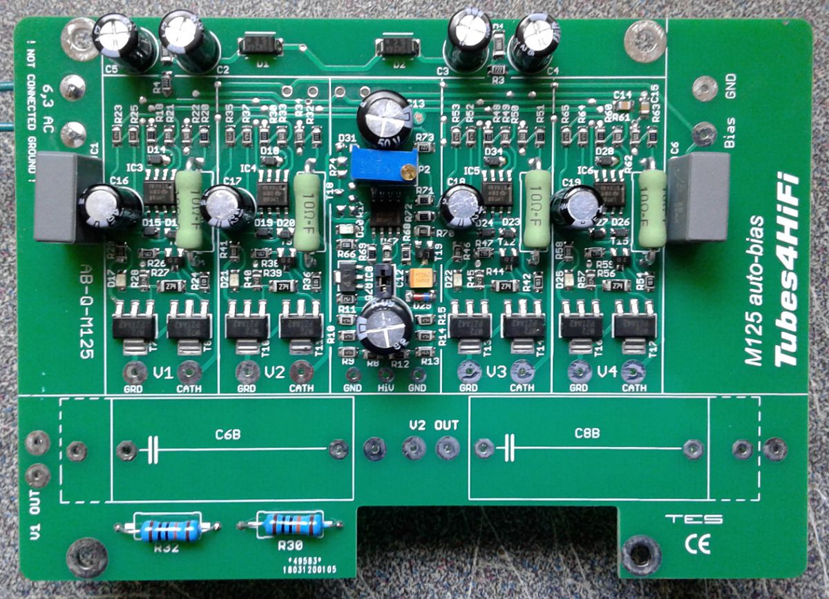
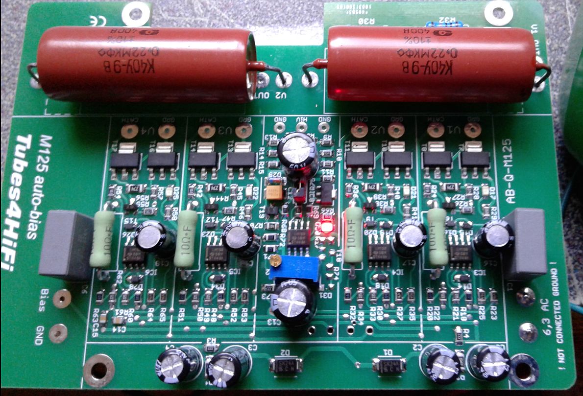
next up is the M125 version, a little more involved for install since you need to add two capacitors and two resistors.
On a stock M125, the output tubes are connected in pairs. With this board EACH tube will be individually controlled to EXACT bias and balance.
I'll supply the resistors, you supply matching caps depending on what you currently have (or let me know and I can order duplicates for you).
Pictured here is the M125 board under test, and showing the big K40Y caps which are slightly larger than the current standard K42Y (green) caps.
One photo shows the mini red LED during warmup. This one came preset for 58ma per tube, I readjusted down to 50ma as per Bob's current recommendation,
although most KT88 amps are fine with 55-65ma so you could just leave it as is. That was about 1.5 turns CCW. Same nice slow 40 second ramp up.
Roy Mottram- Admin
- Posts : 1839
Join date : 2008-11-30
- Post n°23
Re: Auto-Bias board on Roy's website?
for the M125s which are running two pairs of output tubes, you need to add two capacitors and two resistors, so that EACH tube can be controlled individually
Roy Mottram- Admin
- Posts : 1839
Join date : 2008-11-30
- Post n°24
Re: Auto-Bias board on Roy's website?
yes, the ten ohm resistors on the auto-bias board replace the ones that were in the amp originally, in the same location, so they still have the same function.
It's nearly impossible to blow one of these out, as they are 1w resistors, and if you have 0.5v of bias running thru ten ohms, that is 50ma x .5v = 25mw.
To blow out a 1w resistor would require more than 300ma of tube current (300ma x 3v= 0.9 watts).
Of course with a functioning auto-bias circuit, this would NEVER happen. If the tube goes bad and tries to run-away with current, the auto-bias circuit will set the current thru the tube at zero immediately.
This is one of the two huge benefits of auto-bias, you should never ever lose a tube due to red-plating. The other benefits of course are never having to set bias, and always having PERFECT bias and balance.
Perfect output symmetry, minimal distortion.
jfine- Posts : 152
Join date : 2017-06-19
- Post n°25
Re: Auto-Bias board on Roy's website?
So for the M125's, once the boards are completely installed, what is the best way to check the bias? Power it up, do I need any tubes installed, I noticed the positive test pad next to the bias adjustment, but do I just ground the other lead to chassis, etc., is that it?