by mazeeff Fri May 04, 2018 7:09 am
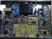
The problem of what happens when the auto-bias circuit encounters a tube with a plate to cathode short can be easily tested by Roy and/or Pavel. With the power off, remove a output tube, and short the plate to cathode, with a large jumper. This would emulate a common problem associated with redplating, where the excess heat of redplating results in metal fatigue, and quite often a short. This type of failure would put 400-500 volts on the cathode, and would normally vaporize the 10 ohm resistor. With eye protection, and a fire suit, flip on the power and see what happens. If the silicon based current limiter and/or the 10 ohm resistor fails, we have a problem. If the circuit works as Roy described in post #79, and limits the current, then we are fine. The alternative, is for Roy or Pavel to disclose part numbers associated with the current limiting circuit. With that information, we could quickly determine if the circuit can withstand a 500v short. In the past 10 years, I have had three tubes fail with a internal short like this, and two times it took out the 10 ohm resistor. Based on reading the forum, a number of folks have blown a 10 ohm resistor, like myself. It is not a rare event. I have wondered, if Roy purposely designed the VTA with the 10 ohm resistor external, because it is easier to replace when it is soldered to a socket and ground. Without an answer to this, we will just have to wait until one of the early adopters encounters a tube failure resulting in a short!
PS: Please do not take my posts as a criticism, in any way. I am a old retired EE, who was taught the value of being a "devil's advocate" early on. We used to hold VERY tough design reviews, where my EE peers were encouraged to find faults in my designs. Saved my Bacon more than once!


 jwb474