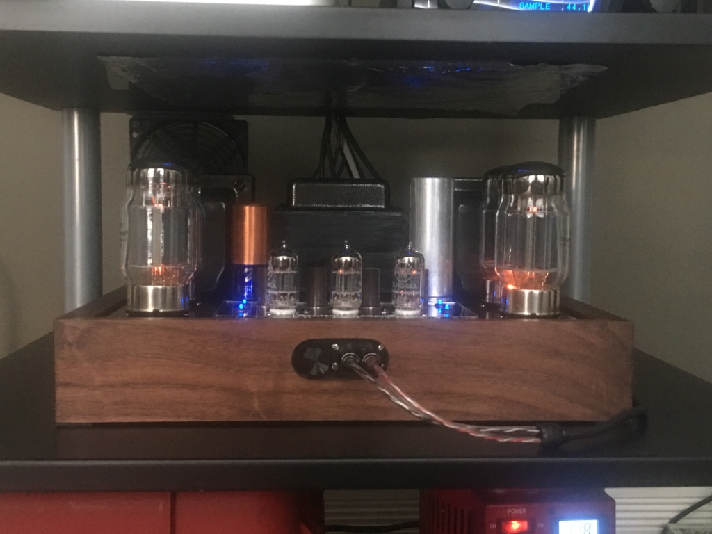
 by Roy Mottram Thu Feb 14, 2019 1:42 pm
the lastest instructions from Pavel still seem to be wrong, V1 OUT is actually V1 GRD (grid), same for V2 OUT, V3 OUT, V4 OUT.
Also, the steps 11-14 are wrong!! The output tube grids actually connect to the VTA driver board, same as before, not directly to the AB board!
Should be
11. Re-connect the Rg1 wire from the VTA driver board to pin 6 in the V1 socket
12. Re-connect the Rg2 wire from the VTA driver board to pin 6 in the V2 socket
13. Re-connect the Rg3 wire from the VTA driver board to pin 6 in the V3 socket
14. Re-connect the Rg4 wire from the VTA driver board to pin 6 in the V4 socket
updated/corrected instructions for the ST70-ST120 auto-bias are here on my website
www.tubes4hifi.com/ST70-AB.pdfthe instructions for the M125 were correct unless someone else can find an error that I don't see


 I LOVE MY ST120


