The Dynaco Tube Audio Forum

Would you like to react to this message? Create an account in a few clicks or log in to continue.
The Dynaco Tube Audio Forum

Dedicated to the restoration and preservation of all original Dynaco tube audio equipment - Customer support for Tubes4hifi VTA tube amp and preamp kits and all Dynakitparts.com products


+2
Bob Latino
corndog71
6 posters

    Bias question

    avatar
    Skelt


    Posts : 25
    Join date : 2013-08-11

    Bias question Empty Bias question

    Post by Skelt Tue Oct 13, 2020 7:58 am

    The following thread has several schematics that are relevant to the following discussion. Please do not attempt to duplicate this amp or any circuit based on these drawings. Drawings have omissions and may contain errors that could result in unsafe operation.


    Help me understand this amp.
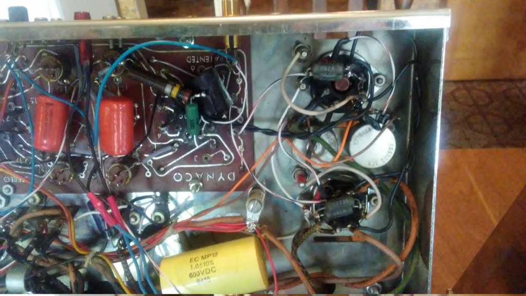
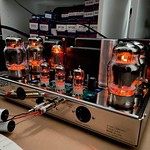
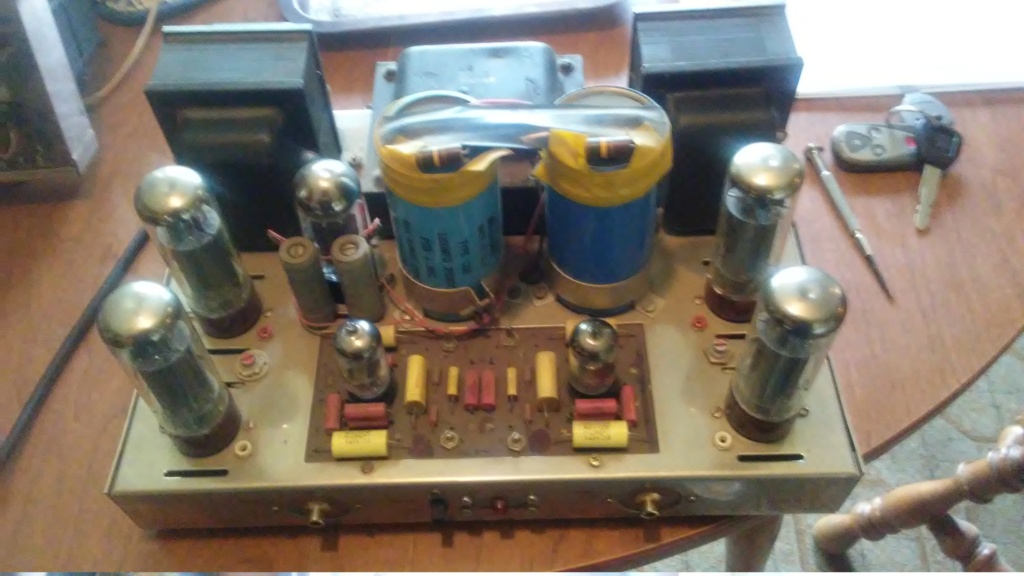
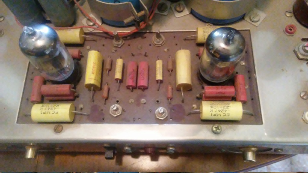
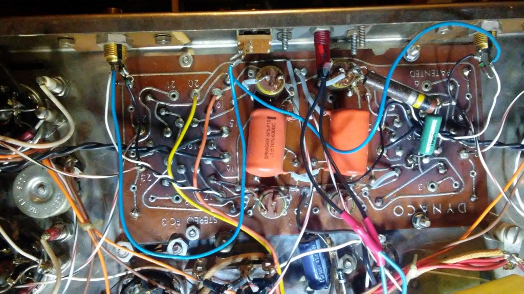
    As you can see I have a very modified st70.
    I've been using it off an on for over 6 years.
    It plays and sounds very good compared to a recapped and otherwise stock st70.

    I recently changed a resistor on the driver board bc of a garbled channel.
    And now I want to be sure the bias is set correctly.
    Bias voltage is currently set to .25v and the can be adjusted to a max of .5v.  
    A list of mods that my untrained eye can see.

    1. the power supply has larger cap. values.
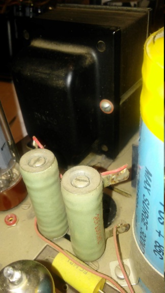
    2. the choke has been changed and moved to the top of chassis
    3. a relay added. The rectifier is wired to this.
    4. The preamp sockets removed and changed to rca jacks.
    5. Four trim pots added to the pcb.
    6. There is a 10k bias pot for each el 34.
    7. Each of the 4 bias resistors measures 35 ohms.


    How do I tell if it is wired for triode or pentode operation?
    Would that affect the bias voltage?
    Bias question 10122010
    Bias question 10122011
    Bias question 10132010


    Last edited by Skelt on Fri Oct 16, 2020 3:55 pm; edited 2 times in total (Reason for editing : Added disclaimer)
    avatar
    Skelt


    Posts : 25
    Join date : 2013-08-11

    Bias question Empty Re: Bias question

    Post by Skelt Tue Oct 13, 2020 8:01 am

    OBias question 10122015
    Bias question 10122014
    avatar
    Guest
    Guest


    Bias question Empty Re: Bias question

    Post by Guest Tue Oct 13, 2020 8:54 am

    .


    Last edited by PeterCapo on Mon Nov 30, 2020 6:17 pm; edited 1 time in total
    avatar
    Guest
    Guest


    Bias question Empty Re: Bias question

    Post by Guest Tue Oct 13, 2020 9:05 am

    .


    Last edited by PeterCapo on Mon Nov 30, 2020 4:41 pm; edited 1 time in total
    avatar
    Skelt


    Posts : 25
    Join date : 2013-08-11

    Bias question Empty Re: Bias question

    Post by Skelt Tue Oct 13, 2020 10:04 am

    I really don't want to strip it down and rebuild.
    Mostly I want to understsnd what I have so if or when problems comes up I can take care of them.
    Its at least for now my goto amp for 2ch vinyl.

    I appreciate the safety concerns.
    The amp has a 3 prong cord however the ground is not connected. Should it be connected to the chassis?
    I've never detected a voltage difference between its chassis to a preamp anytime I've measured.
    Im using the pre outs on a rotel rx402.

    It maybe difficult to back track thru these mods but I have time at the moment and a stock st70 so I can do direct comparisons.

    The only problem I've had was that open resistor.
    It took me a couple of days to get my o-scope and signal gen working and find/replace the resistor. Now I want to learn more about these mods.

    The bias was set to a 1/4 volt when I got it.
    When the resistor was going out I started to swing the pots to clean as the start of my diagnosis.
    Adjusting by ear? Anywhere between .25 and .5v sounds fine with .5 being a little brighter.
    How do I tell if a tube is red plating?
    avatar
    Guest
    Guest


    Bias question Empty Re: Bias question

    Post by Guest Tue Oct 13, 2020 10:19 am

    .


    Last edited by PeterCapo on Mon Nov 30, 2020 4:42 pm; edited 2 times in total
    peterh
    peterh


    Posts : 1832
    Join date : 2012-12-25
    Location : gothenburg, sweden

    Bias question Empty Re: Bias question

    Post by peterh Tue Oct 13, 2020 10:23 am

    Skelt wrote: I really don't want to strip it down and rebuild.
    Mostly I want to understsnd what I have so if or when problems comes up I can take care of them.
    Its at least for now my goto amp for 2ch vinyl.

    I appreciate the safety concerns.
    The amp has a 3 prong cord however the ground is not connected. Should it be connected to the chassis?
    I've never detected a voltage difference between its chassis  to a preamp anytime I've measured.
    Im using the pre outs on a rotel rx402.

    It maybe difficult to back track thru these mods but I have time at the moment and a stock st70 so I can do direct comparisons.

    The only problem I've had was that open resistor.
    It took me a couple of days to get my o-scope and signal gen working and find/replace the resistor. Now I want to learn more about these mods.

    The bias was set to a 1/4 volt when I got it.
    When the resistor was going out I started to swing the pots to clean as the start of my diagnosis.
    Adjusting by ear? Anywhere between .25 and .5v sounds fine with .5 being a little brighter.
    How do I tell if a tube is red plating?

    As i understand you there is individual sense resistors between each EL34 and ground. Each
    of them measures 35 ohms. The current wanted in each EL34 is 40-50mA
    This tells me that you should adjust your bias to 1.25V
    0.5 Volt across a 35 ohm gives 14mA !!

    I see that you have 2 choices here :
    - examine and build a schematic that corresponds to the amp
    or
    - rip it down and rebuild according to Dynaco manual ( which is no big thing as you
    have most of the stuff already)


    avatar
    Skelt


    Posts : 25
    Join date : 2013-08-11

    Bias question Empty Re: Bias question

    Post by Skelt Tue Oct 13, 2020 10:56 am

    Yes the bias seems very odd.

    If I lifted the ground on one of the 35 ohm resistors could I use an ammeter to measure the plate current? Or is that a waste of time and plate current is simply an ohms law calculation.

    I have some reading and work to do.
    Agreed a schematic and gfci outlets are needed. Both will take some time.
    I'm sure ill be back with more questions.


    avatar
    Guest
    Guest


    Bias question Empty Re: Bias question

    Post by Guest Tue Oct 13, 2020 11:57 am

    .


    Last edited by PeterCapo on Mon Nov 30, 2020 4:42 pm; edited 1 time in total
    avatar
    Skelt


    Posts : 25
    Join date : 2013-08-11

    Bias question Empty Re: Bias question

    Post by Skelt Tue Oct 13, 2020 1:02 pm

    Thanks, that's what I thought. I'm over think things a bit.

    Ill start with drawings the ps.
    The rectifier is a. JJ gz34s but its wiring doest match my stock one.


    Bias question 10132011

    avatar
    Guest
    Guest


    Bias question Empty Re: Bias question

    Post by Guest Tue Oct 13, 2020 1:09 pm

    .


    Last edited by PeterCapo on Mon Nov 30, 2020 4:42 pm; edited 1 time in total
    avatar
    Skelt


    Posts : 25
    Join date : 2013-08-11

    Bias question Empty Re: Bias question

    Post by Skelt Tue Oct 13, 2020 1:27 pm

    There's quite a few diodes near some of the caps.
    I'm thinking it may be SS rectifier and the gz34 with the relay  is providing a time delay circuit.
    This may take me some time to draw it out.

    Here is my un modified one

    Bias question 10132013
    avatar
    Guest
    Guest


    Bias question Empty Re: Bias question

    Post by Guest Tue Oct 13, 2020 1:35 pm

    .


    Last edited by PeterCapo on Mon Nov 30, 2020 4:43 pm; edited 1 time in total
    avatar
    Skelt


    Posts : 25
    Join date : 2013-08-11

    Bias question Empty Re: Bias question

    Post by Skelt Tue Oct 13, 2020 2:09 pm

    For sure I go back and forth to the drawings.
    My "stock" one has been recapped both the ps and signal.
    The wiring was straightened out at the same time(not by me)
    corndog71
    corndog71


    Posts : 840
    Join date : 2013-03-19
    Location : It can get windy here

    Bias question Empty Re: Bias question

    Post by corndog71 Tue Oct 13, 2020 2:31 pm

    I wouldn’t trust a frankenamp like that unless I did the mods myself.

    I recommend stripping it down and rebuilding it with a VTA driver board. You would then know exactly what you have and if any problems come up the this forum can be a great help.

    VintageRulez likes this post

    avatar
    Skelt


    Posts : 25
    Join date : 2013-08-11

    Bias question Empty Re: Bias question

    Post by Skelt Tue Oct 13, 2020 7:07 pm

    If this amp was having serious difficulties I would buy a VTA board. Anyway I like they way it sounds and I'm up to the challenge to back engineer this one.


    An update
    The gz34 was doing nothing not even lit up.
    To be sure I put a signal to the amp and sure enough it plays with it removed. The relay seems to be another diversion. I can't find a circuit path or condition that would cause it to switch. The coil is wired to empty pins on the rectifier socket.
    avatar
    Guest
    Guest


    Bias question Empty Re: Bias question

    Post by Guest Tue Oct 13, 2020 7:16 pm

    .


    Last edited by PeterCapo on Mon Nov 30, 2020 4:43 pm; edited 1 time in total
    avatar
    Skelt


    Posts : 25
    Join date : 2013-08-11

    Bias question Empty Re: Bias question

    Post by Skelt Wed Oct 14, 2020 9:46 am

    Power supply summery and schematic

    I've omitted the heater circuits and 3 of the bias pots for clarity.
    The rectifier consists of 4 diodes and 4 resistors.
    I'm not going to map them out. There is 430 vdc output there.
    There's a pair of series wired 1k wire wound resistors in place of the choke. Are they providing inductance?
    The voltages stray a little from book values

    Voltage at
    A is 300
    B is 320
    C is 350

    Bias question 10202011
    Bias question 10142012


    Last edited by Skelt on Tue Oct 20, 2020 3:57 pm; edited 1 time in total
    avatar
    Skelt


    Posts : 25
    Join date : 2013-08-11

    Bias question Empty Re: Bias question

    Post by Skelt Thu Oct 15, 2020 7:04 am

    I took a look at the output stage yesterday.

    Everything matches the dyna pdf except for

    1. Each tube individually biased with a 35 ohm resistors.
    2. Eyelet 11 is not connected to the OT.
    3. Eyelets 11 and 12 are shorted together and connected to the 8 ohm tap.
    4. Coupling caps are .22uF.

    Would any of these changes affect the bias setting?
    avatar
    Guest
    Guest


    Bias question Empty Re: Bias question

    Post by Guest Thu Oct 15, 2020 7:54 am

    .


    Last edited by PeterCapo on Mon Nov 30, 2020 4:43 pm; edited 1 time in total
    avatar
    Skelt


    Posts : 25
    Join date : 2013-08-11

    Bias question Empty Re: Bias question

    Post by Skelt Thu Oct 15, 2020 8:28 am

    I'm using a Simpson 260 so 35ohms may be 37.  makes little difference for this discussion.
    The bias resistors are marked Dale v750  y7736. A pair is paralleled at each el34.
    The bias pots are wired directly to the 1k resistor and the pair of 270k resistors are removed from the pcb.


    Bias question 10152010
    Bias question 10152011
    peterh
    peterh


    Posts : 1832
    Join date : 2012-12-25
    Location : gothenburg, sweden

    Bias question Empty Re: Bias question

    Post by peterh Thu Oct 15, 2020 8:30 am

    Skelt wrote:I took a look at the output stage yesterday.

    Everything matches the dyna pdf except for

    1.  Each tube individually biased with a 35 ohm resistors.
    2.  Eyelet 11 is not connected to the OT.
    3.  Eyelets 11 and 12 are shorted together and connected to the 8 ohm tap.
    4. Coupling caps are .22uF.

    Would any of these changes affect the bias setting?
    As for (1) :
    that implies that you should have 1.25V across each resistor to get 41mA bias ( which is
    quite low, up to 55mA is ok)
    (2 and 3)
    The feedback circuits are altered. Unless one can verify it's effectiveness with scope
    and function generator this is suspect. Lacking these resources the best you can do is
    restore to original configuration.
    (4) if the grid resistors are still 270 k then the caps are too big. Should be 0.1uF

    Skelt likes this post

    avatar
    Skelt


    Posts : 25
    Join date : 2013-08-11

    Bias question Empty Re: Bias question

    Post by Skelt Thu Oct 15, 2020 8:45 am

    Ill know more when I get the driver board drawn as for now I think the 270k resistors have been removed.

    Stability was mentioned. The amp does begin to breakup when I lean on the volume. A quick voltage check at the speaker connections shows about 4 or 5v peaks before distortion sets in. I'm driving Klipschorns updated with new drivers and AK4 crossovers.
    avatar
    Guest
    Guest


    Bias question Empty Re: Bias question

    Post by Guest Thu Oct 15, 2020 8:48 am

    .


    Last edited by PeterCapo on Mon Nov 30, 2020 4:43 pm; edited 1 time in total
    avatar
    Skelt


    Posts : 25
    Join date : 2013-08-11

    Bias question Empty Re: Bias question

    Post by Skelt Thu Oct 15, 2020 8:53 am

    PeterCapo wrote:
    Coupling capacitors increased to 0.22µF may be a consequence of the classic Van Alstine article from the 1980s where it was pointed out that the coupling cap value affected one of the perceived shortcomings of the original design.  Or he just decided about it on his own.  However, simply increasing the value of the coupling capacitors is also said to decrease the amplifier's stability.

    Do you have a link or know where to find this article?

    Sponsored content


    Bias question Empty Re: Bias question

    Post by Sponsored content


      Current date/time is Fri Apr 19, 2024 12:51 pm