The Dynaco Tube Audio Forum

Would you like to react to this message? Create an account in a few clicks or log in to continue.
The Dynaco Tube Audio Forum

Dedicated to the restoration and preservation of all original Dynaco tube audio equipment - Customer support for Tubes4hifi VTA tube amp and preamp kits and all Dynakitparts.com products


3 posters

    Finished My VTA Driver Board

    Tom Pickett
    Tom Pickett


    Posts : 203
    Join date : 2020-11-22
    Age : 58
    Location : Texas

    Finished My VTA Driver Board Empty Finished My VTA Driver Board

    Post by Tom Pickett Fri Apr 16, 2021 12:59 pm

    Finished My VTA Driver Board

    Good morning everyone.... I hope all of you are having a good day and safe.

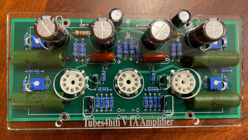
    Last night I started on my VTA driver board and got everything put together. I've done a few modifications on the board because I'm going to mount the board on the outside of the chassis up on some standoffs so I can display all of the electronic components on the board especially those nice beautiful green Russian capacitors. Plus I’m going to add a sheet insulator to the bottom of the VTA board to keep it insulated for the top of the chasses. I also did a few modifications on the clear acrylic cover.

    Let me just say this board is absolutely beautiful. This is a very professional grade board that has nice heavy duty traces and is coated with some type of clear epoxy that will keep the board from corroding or turning colors with time.

    One thing else that I want to say before I end this post is if you are a newbie and/or a beginner building one of these amplifiers take your time and follow the instructions that Bob has laid out for you in the package before you decide if or when to make your own modifications.

    Have A good day and clear skies everyone and stay safe.

    Tom

    Finished My VTA Driver Board Img_5710
    Finished My VTA Driver Board Img_5711
    Finished My VTA Driver Board Img_5712
    Finished My VTA Driver Board Img_5713
    Finished My VTA Driver Board Img_5714


    Last edited by Tom Pickett on Fri Apr 16, 2021 2:26 pm; edited 1 time in total
    Tom Pickett
    Tom Pickett


    Posts : 203
    Join date : 2020-11-22
    Age : 58
    Location : Texas

    Finished My VTA Driver Board Empty Re: Finished My VTA Driver Board

    Post by Tom Pickett Fri Apr 16, 2021 1:34 pm

    There's one other thing that I would like to add that's very important that is a practice that I do every time I'm working on a piece of electronic equipment.

    Before installing any components take a multimeter and check your tolerances on all of your resistors and capacitors before and after you install them because sometimes every once in a while a bad component will come your way and you'll catch it before you install it.
    Believe me it will save you a lot of headaches later on in your build.

    All of the components that I received from Bob were in exexcellent condition and were within the normal tolerances.
    Bob Latino
    Bob Latino
    Admin


    Posts : 3260
    Join date : 2008-11-26
    Location : Massachusetts

    Finished My VTA Driver Board Empty Re: Finished My VTA Driver Board

    Post by Bob Latino Fri Apr 16, 2021 1:48 pm

    Tom,

    1. those four green .22 uF Russian PIO caps
    2. the two brown .22 uF @ 630 volt caps near the center of the board
    3. the two black 100 uF @ 100 volt caps on the back edge of the driver board
    4. the diode
    5. the jumper wire for R39

    should all be installed on the BOTTOM OF THE DRIVER BOARD so that the board will fit into the amp properly and also so that the driver board cover will fit down on the top surface of the chassis.

    Bob
    Tom Pickett
    Tom Pickett


    Posts : 203
    Join date : 2020-11-22
    Age : 58
    Location : Texas

    Finished My VTA Driver Board Empty Re: Finished My VTA Driver Board

    Post by Tom Pickett Fri Apr 16, 2021 1:58 pm

    Bob Latino wrote:Tom,

    1. those four green .22 uF Russian PIO caps
    2. the two brown .22 uF @ 630 volt caps near the center of the board
    3. the two black 100 uF @ 100 volt caps on the back edge of the driver board
    4. the diode
    5. the jumper wire for R39

    should all be installed on the BOTTOM OF THE DRIVER BOARD so that the board will fit into the amp properly and also so that the driver board cover will fit down on the top surface of the chassis.

    Bob

    Bob I'm going to install the driver board on top of the chassis on some standoffs so I can display all of the nice components. I also modified the clear acrylic cover to fit the driver board.
    Just a few mods that I want to make on my own.
    Thanks Bob

    Tom
    Bob Latino
    Bob Latino
    Admin


    Posts : 3260
    Join date : 2008-11-26
    Location : Massachusetts

    Finished My VTA Driver Board Empty Re: Finished My VTA Driver Board

    Post by Bob Latino Fri Apr 16, 2021 2:09 pm

    OK - I neglected to read your post where you said that you were going to install the board on standoffs outside (above) the chassis. Sure, you could do that. I am curious to see how the board looks set up like that ?

    Bob

    Tom Pickett likes this post

    Tom Pickett
    Tom Pickett


    Posts : 203
    Join date : 2020-11-22
    Age : 58
    Location : Texas

    Finished My VTA Driver Board Empty Re: Finished My VTA Driver Board

    Post by Tom Pickett Fri Apr 16, 2021 2:22 pm

    Bob Latino wrote:OK - I neglected to read your post where you said that you were going to install the board on standoffs outside (above) the chassis. Sure, you could do that. I am curious to see how the board looks set up like that ?

    Bob

    Bob, I would also like to say that I absolutely love the beautiful components that you have chosen for this build/board and of course the driver board itself it is so professionally done and so nice. To me it's worth doing a few carefully chosen extra mods to display the beauty of the board and it's components in a different fashion.

    By the time I'm done I hope that it looks like a work of art and of course at the same time keep and make it safe.

    Thanks Bob... I always expect you to be on top of things because in this business that's what we do :-)

    Tom


    Last edited by Tom Pickett on Fri Apr 16, 2021 4:31 pm; edited 1 time in total
    Tom Pickett
    Tom Pickett


    Posts : 203
    Join date : 2020-11-22
    Age : 58
    Location : Texas

    Finished My VTA Driver Board Empty Re: Finished My VTA Driver Board

    Post by Tom Pickett Fri Apr 16, 2021 4:27 pm

    I just now finished my VTA–TDR (Time Delay Relay) board.

    As you can see this board (just like the others) is also very well-made with nice traces and a clear epoxy coating to protect the board from the elements.

    The only components that I have not installed is the red and green leds because I'm going to install them on the front-face of the amp so I know when the TDR is switched on or off.

    Finished My VTA Driver Board Img_5715
    Finished My VTA Driver Board Img_5716
    avatar
    Rbertalotto


    Posts : 98
    Join date : 2021-02-25

    Finished My VTA Driver Board Empty Re: Finished My VTA Driver Board

    Post by Rbertalotto Fri Apr 16, 2021 7:39 pm

    I want to relocate the red and green LEDs to the front of the cabinet I built. Great minds think alike!

    Tom Pickett likes this post

    Tom Pickett
    Tom Pickett


    Posts : 203
    Join date : 2020-11-22
    Age : 58
    Location : Texas

    Finished My VTA Driver Board Empty Re: Finished My VTA Driver Board

    Post by Tom Pickett Fri Apr 16, 2021 8:05 pm

    Rbertalotto wrote:I want to relocate the red and green LEDs to the front of the cabinet I built. Great minds think alike!

    Hahahahaha...... Finished My VTA Driver Board 1f600

    Yes.... Months ago I was making plans to do just that and to mount the driver board outside of the chassis.

    To me, that driver board is so beautiful and so well made that it needs showing off. I just hope that it looks as good as I imagined. I’ve seen other people do it before so it's nothing new.

    When you look at the original design the board is mounted on the inside and they originality intended on showing off the components but some of the components are hidden because of the way the board is mounted and some of the coupling capacitors will short out against the chassis if you're not careful.

    This modification I have made eliminates all of that and puts the driver board directly outside of the chasses to where you can see all of those beautiful components and caps alongside the tubes.

    I also have some other things in mind... We'll see how it turns out :-)

    avatar
    Guest
    Guest


    Finished My VTA Driver Board Empty Re: Finished My VTA Driver Board

    Post by Guest Sat Apr 17, 2021 10:57 am

    Finished My VTA Driver Board 2019-015

    I had my blue lights moved to the top of the clear plastic cover.
    avatar
    Rbertalotto


    Posts : 98
    Join date : 2021-02-25

    Finished My VTA Driver Board Empty Re: Finished My VTA Driver Board

    Post by Rbertalotto Sat Apr 17, 2021 11:07 am

    Where are you driving the blue lights from? Are they LEDs?
    avatar
    Guest
    Guest


    Finished My VTA Driver Board Empty Re: Finished My VTA Driver Board

    Post by Guest Sat Apr 17, 2021 11:16 am

    the autobias board
    avatar
    Rbertalotto


    Posts : 98
    Join date : 2021-02-25

    Finished My VTA Driver Board Empty Re: Finished My VTA Driver Board

    Post by Rbertalotto Sat Apr 17, 2021 11:20 am

    Don't have auto bias board on my ST120......

    I like the look!
    avatar
    Rbertalotto


    Posts : 98
    Join date : 2021-02-25

    Finished My VTA Driver Board Empty Re: Finished My VTA Driver Board

    Post by Rbertalotto Sat Apr 17, 2021 11:24 am

    BTW...Can I leave the LEDs on the relay board and simply add another set in parallel ?

    Is there enough to drive two LEDS in each position?

    What are the values of the LEDS if anyone knows.

    Thanks

    Tom Pickett likes this post

    Tom Pickett
    Tom Pickett


    Posts : 203
    Join date : 2020-11-22
    Age : 58
    Location : Texas

    Finished My VTA Driver Board Empty Re: Finished My VTA Driver Board

    Post by Tom Pickett Sat Apr 17, 2021 12:23 pm

    That's a good question.

    Yes I do believe that there is enough power/current on that board to run two more LED's.
    But I don't know how sensitive the IC chip is or the transistor that switches off and on the power through the relay switch.

    Let me look up the data sheet on that IC and transistor.

    Down below is the data sheet on that IC NE555P or cross reference NTE955M and Transistor 2N3904.

    You may have to do a little experimenting but I wouldn't go no more than two extra LED's so you're not putting too much load or stress on the IC chip or the transistor. Most of the time those LED's especially the small ones typically only draw 20mA of current so I believe it will be safe. Plus run the LED's in parallel so you don't lose any brightness. That will be 40mA Per 2 LED's.

    I would also ask Bob... I'm sure he has a lot of experience with the layout of that board and more than likely he's been asked the same question a number of times lol

    IC NE555P or cross reference NTE955M Datasheet: https://www.nteinc.com/specs/900to999/pdf/nte955.pdf

    Transistor 2N3904 or cross reference NTE123AP: https://www.nteinc.com/specs/100to199/pdf/nte123ap.pdf
    Tom Pickett
    Tom Pickett


    Posts : 203
    Join date : 2020-11-22
    Age : 58
    Location : Texas

    Finished My VTA Driver Board Empty Re: Finished My VTA Driver Board

    Post by Tom Pickett Sun Apr 18, 2021 9:16 pm

    Good evening everyone..... I hope all of you are having a good day and all of you are safe.

    At the moment I am at a stopping point on my build because there are a few modifications that I want to make to the back of the chassis and I don't want to assemble any hardware on the chasses and it gets metal shavings everywhere on the tube sockets and other components.

    In the back I'm going to install a three prong AC power entry module. This will make it very convenient to unplug the amp from the main power cord going to the AC outlet.

    I haven't completely decided yet if I'm going to install an extra right and left channel RCA input jack on the back but I'm not going to do these modifications until the first of the month. I have to take the chassis down to a machine shop to have them do the work professionally for me so it gets done correctly.

    All of you have a good day and take care and stay safe my friends.

    Finished My VTA Driver Board S-l50012
    Finished My VTA Driver Board S-l50013

    Sponsored content


    Finished My VTA Driver Board Empty Re: Finished My VTA Driver Board

    Post by Sponsored content


      Current date/time is Thu Mar 28, 2024 5:49 pm