

I'm still unsure about that amp being a 'MkIII' vs a 'MkII' with some work done to upgrade it. The 4/8/16 ohm output transformer is definitely MkIII! BUT, that 'add-on' choke to the top of the chassis, that is definitely NOT MkIII, at least from a 'stock' build perspective. The MkIII choke was located under the chassis. So, a couple of good clean pics of both the 'top' surface, as well as the underside, that would help confirm this. I'd note that the use of EL34s is also 'MkII' vs MkIII...... so, again, makes the question still out there in my mind!!
+6
johnmeyer
danielrhall
corndog71
peterh
Bob Latino
solderblob
10 posters
Restore Three Mark II Amps

Wharfcreek- Posts : 43
Join date : 2017-07-15
Solder Slinger- Posts : 36
Join date : 2009-05-24
Therefore, even if the resistor value is off, as long as I know what it is, and as long as it is stable, I can adjust for a different voltage so that the current across the actual measured resistance equals 130 mA, per the Mark II bias instructions.
Don't know where you got the 130 ma plate current on EL-34s but that's way too high. I believe Dynaco originally biased them about 45-50 ma each. I personally run 6550s or KT-90s at about 40 ma, plus I'm running them in triode mode. I think they sound better when not run too hard, plus they'll last longer.
Just my 2 cents.
Also, forgot to mention in my first post... add a CL-80 NTC on the power cord. Per old timers, you potentially increase the tube heater life by 4X by doing a somewhat slow turn on of the tube heaters.
Good Luck,
-Ed

danielrhall- Posts : 4
Join date : 2021-05-27
Location : Raymond, NH USA
That is certainly one of its purposes and the resistance value was chosen as part of the clever, patented "Biaset" scheme devised by David Hafler to make bias setting easier for home audio hobbyists. But it has another purpose too: distortion reduction. See the sixth paragraph in this article on page 58 by Hafler regarding the unbypassed common-cathode resistor and its effect on degenerative (negative) feedback.johnmeyer wrote:Thanks for reminding me to do that. I forgot about it. If you look at my posts above about the very non-standard amp (on the big chassis) you'll see that I found it had no bias resistor at all. I believe the point of the resistor is to allow you to set the bias current by measuring voltage across a small resistor. Therefore, even if the resistor value is off, as long as I know what it is, and as long as it is stable, I can adjust for a different voltage so that the current across the actual measured resistance equals 130 mA, per the Mark II bias instructions.Solder Slinger wrote:5.) Check the resistor attached to pin 8 of both the output tubes, 11.2 ohm in the Mk 3, I believe it is a 12 ohm in the Mk 2 but can't be sure. If this is off, it can greatly affect the tube bias, replace it with a 1% 11.2 ohm part from DynaKit Parts. This must be accurate to get the correct tube bias.
I think the goal is to get 130mA and the voltage across a precision 12 ohm resistor is the means to achieve that end.
https://worldradiohistory.com/Archive-Radio-Electronics/50s/1958/Radio-Electronics-1958-01.pdf
danielrhall- Posts : 4
Join date : 2021-05-27
Location : Raymond, NH USA
That's the plate current through the common cathode resistor for both output tubes in the push-pull configuration, so it's 65 ma per EL34. But I agree...that's still driving them much too hard, even though that's the resulting value specified by the biasing procedure in the Dynakit MKII Instruction Manual. With the MKII's spec of 460 vdc plate voltage and 65 ma of plate current, that represents 29.9 watts of plate dissipation. That's well above the design center value for the EL34. The Mullard EL34 tubes supplied with the MKII when it was new could probably take that abuse (but why would you?), but contemporary EL34s are unlikely to last long driven that hard. The Dynaco ST-70 also used EL34 output tubes but it was specified to be run with only 50 ma of plate current.Solder Slinger wrote:Therefore, even if the resistor value is off, as long as I know what it is, and as long as it is stable, I can adjust for a different voltage so that the current across the actual measured resistance equals 130 mA, per the Mark II bias instructions.
Don't know where you got the 130 ma plate current on EL-34s but that's way too high. I believe Dynaco originally biased them about 45-50 ma each. I personally run 6550s or KT-90s at about 40 ma, plus I'm running them in triode mode. I think they sound better when not run too hard, plus they'll last longer.
johnmeyer- Posts : 30
Join date : 2021-06-18
Age : 71
Location : Central Coast, CA
Yeah, I don't think the amp I "finished" today (these are never finished ...) is a Mark III. I looked at my original Mark II manual and it shows 4/8/16 speaker outputs, so that isn't a Mark III identifier.
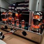
As for showing a picture of the tops, I already did that. The huge choke can be seen -- along with the tops of the other three amps -- in the picture I referenced in post #1 in this thread. It is over in the Photos section of this forum. Here is a link so you don't have to hunt for it:
https://dynacotubeaudio.forumotion.com/t4696-three-mark-ii-amps-my-friend-wants-me-to-restore
You'll want to click on the picture to see all of it because this forum truncates the photo on my browser. The amp on the right is the one I finished today, and you'll see the large choke installed immediately to the left of the driver board. It is labeled "70 ohms" so it is higher than the 50 ohm resistor it replaces, but I have no idea what the reactive equivalent might be. I'm sure there are bigger chokes out there, but this is the biggest I've come across (in my very limited experience with this sort of thing).
So, the original Dynaco design was to use the voltage and resistor to obtain 130 mA current.
All I know is what I read ...
I think the goal is to get 130mA and the voltage across a precision 12 ohm resistor is the means to achieve that end.
Unfortunately, I could never get it totally stable ...
As for showing a picture of the tops, I already did that. The huge choke can be seen -- along with the tops of the other three amps -- in the picture I referenced in post #1 in this thread. It is over in the Photos section of this forum. Here is a link so you don't have to hunt for it:
https://dynacotubeaudio.forumotion.com/t4696-three-mark-ii-amps-my-friend-wants-me-to-restore
You'll want to click on the picture to see all of it because this forum truncates the photo on my browser. The amp on the right is the one I finished today, and you'll see the large choke installed immediately to the left of the driver board. It is labeled "70 ohms" so it is higher than the 50 ohm resistor it replaces, but I have no idea what the reactive equivalent might be. I'm sure there are bigger chokes out there, but this is the biggest I've come across (in my very limited experience with this sort of thing).
I posted this direct quote from the original manual in post #42, but here it is again:Solder Slinger wrote:Don't know where you got the 130 ma plate current on EL-34s but that's way too high. I believe Dynaco originally biased them about 45-50 ma each. I personally run 6550s or KT-90s at about 40 ma, plus I'm running them in triode mode. I think they sound better when not run too hard, plus they'll last longer.
Just my 2 cents.
- "The correct setting of the bias provides a total cathode current of the EL-34 tubes of 130mA. This current through the precision 12 ohm resistor produces a voltage drop of exactly 1.56 volts DC."
So, the original Dynaco design was to use the voltage and resistor to obtain 130 mA current.
All I know is what I read ...
That's a very good idea. I'll do that. Cheap insurance. I'll put it between the cord and the fuse, since it is not a slow blow fuse.Solder Slinger wrote:Also, forgot to mention in my first post... add a CL-80 NTC on the power cord. Per old timers, you potentially increase the tube heater life by 4X by doing a somewhat slow turn on of the tube heaters.
Good Luck,
-Ed
Thanks for reminding me to do that. I forgot about it. If you look at my posts above about the very non-standard amp (on the big chassis) you'll see that I found it had no bias resistor at all. I believe the point of the resistor is to allow you to set the bias current by measuring voltage across a small resistor. Therefore, even if the resistor value is off, as long as I know what it is, and as long as it is stable, I can adjust for a different voltage so that the current across the actual measured resistance equals 130 mA, per the Mark II bias instructions.Solder Slinger wrote:5.) Check the resistor attached to pin 8 of both the output tubes, 11.2 ohm in the Mk 3, I believe it is a 12 ohm in the Mk 2 but can't be sure. If this is off, it can greatly affect the tube bias, replace it with a 1% 11.2 ohm part from DynaKit Parts. This must be accurate to get the correct tube bias.
I think the goal is to get 130mA and the voltage across a precision 12 ohm resistor is the means to achieve that end.
Wow, what a great article. The only amp I ever designed was based on some similar ideas, but in solid state. I can't remember if I saw the original idea in Radio Electronics or Popular Electronics. I built it around 1975. It had a similar feedback scheme.danielrhall wrote:That is certainly one of its purposes and the resistance value was chosen as part of the clever, patented "Biaset" scheme devised by David Hafler to make bias setting easier for home audio hobbyists. But it has another purpose too: distortion reduction. See the sixth paragraph in this article on page 58 by Hafler regarding the unbypassed common-cathode resistor and its effect on degenerative (negative) feedback.
https://worldradiohistory.com/Archive-Radio-Electronics/50s/1958/Radio-Electronics-1958-01.pdf
Unfortunately, I could never get it totally stable ...
Wharfcreek- Posts : 43
Join date : 2017-07-15
John, I think the point here with the bias references above is the in today's world, with the processes and materials used, the 'durability' factor of 'todays' tubes just simply is NOT what it was 50 some years ago. So, while Dynaco did in fact specify a 65ma per-tube bias level, in today's world, that's just not a safe operating point. Particularly when adding the potentially higher plate voltages from the inflated household AC wall voltage. As mentioned, the ST-70 ran it's EL34s at 50ma per tube, as did the MkIVs. Granted, the idea behind the MkII and MkIII were to have more power...... but there's a 'practical' side to all this. I don't recall the exact numbers involved, but I seem to recall that it takes roughly twice as much output power to increase an amp's output volume level (given all else is the same) by just one db. It may be two db, but I'm not splitting hairs. So, to go from 35 watts per side, to 50 or 60.... you're really not gaining all that much.....or so it would seem. So, to put this back in to 'bias' perspective, if you cool the bias down some, from the 65ma per tube to 55ma, or even 50ma, you're probably not going to notice much difference in 'normal' listening circumstances. Pushed hard at the peak output capability, and yea..... you'll possibly be able to make an audible distinction. But who runs their amp 'wide open' all the time? No one I know! Again, all this is 'measurable'..... and when running 'at spec' I'm sure the output transformer is capable of delivering output 'at spec' and within the stated distortion numbers as well. But you may never hear a difference when operating the amp at 55ma vs 65ma.....yet you'll enjoy a longer tube life, and a more reliable unit.
As to the pics in your other thread, it looks to me like the amp on the far right is perhaps a 'true' MkII, where the amp in the middle is perhaps a MkIII. Again, underside shots of both would help. But, as referenced above, the slotted chassis along with the narrow 'rectangular' driver board, both of those pretty much belong to the MkIII world. If the amp on the right IS a MkII but has all 3 outputs (4,8, 16), that would make it either a very late production kit, or more likely a unit that someone 'upgraded' by simply removing the 4/8 ohm OT and replacing it with the 4,8,16, particularly if they were pairing the amp with another MkIII unit. In any case, no Dynaco kit or factory unit EVER came with a choke mounted like that one on the top-side was. That doesn't even appear to be a Dynaco part......looks more like a generic choke from another vendor.
So, glad you got one working. Will be interesting when you get the second one up and running, and compare the two amps. What will you be using to drive the amps for your final testing? I gather from the pics of the Altecs that you'll be using those speakers in your final tests?
johnmeyer- Posts : 30
Join date : 2021-06-18
Age : 71
Location : Central Coast, CA
So you would recommend simply turning down the bias voltage from the original 1.56 volts to 55/65 * 1.56 = 1.32 volts?Wharfcreek wrote: So, to put this back in to 'bias' perspective, if you cool the bias down some, from the 65ma per tube to 55ma, or even 50ma, you're probably not going to notice much difference in 'normal' listening circumstances.
I am doing these for a friend, so they will never drive my Altec 604s.Wharfcreek wrote:So, glad you got one working. Will be interesting when you get the second one up and running, and compare the two amps. What will you be using to drive the amps for your final testing? I gather from the pics of the Altecs that you'll be using those speakers in your final tests?
I've researched this a bit and I have one question: do you mount this on top of the chassis next to the tubes where it can get some air, or do you put it inside the chassis? I would think it would be better up top, in order not to roast everything down below, but I'd then have to figure out how to mount it "out in the open."Solder Slinger wrote:... add a CL-80 NTC on the power cord.
I've now read lots of blogs and watched a few videos and the heat appears to be an issue. Everything else about the mod seems quite positive.
Wharfcreek- Posts : 43
Join date : 2017-07-15
1.35v, yup!
corndog71- Posts : 840
Join date : 2013-03-19
Location : It can get windy here
Meanwhile other amp makers use a 10 ohm or even 1 ohm resistor to measure the bias. The value of the resistor isn’t an issue. The goal is to get an accurate measurement. I like using a 10 ohm 1% resistor myself as it doesn’t involve math. 0.50 VDC = 500mA of current.
Also, tube manufacturers have said lower bias means longer life. So I bias my power tubes with .40v of idle current each and they still sound great.
Also, tube manufacturers have said lower bias means longer life. So I bias my power tubes with .40v of idle current each and they still sound great.
johnmeyer- Posts : 30
Join date : 2021-06-18
Age : 71
Location : Central Coast, CA
I finished the final amp of the three and it works. B+ and bias voltages are textbook.
I am sure that the owner of these amps will want to do some of the upgrades and mods discussed in this thread, and elsewhere in this forum, so I will probably be back with more questions at some point.
Thanks to everyone who helped!!!
I am sure that the owner of these amps will want to do some of the upgrades and mods discussed in this thread, and elsewhere in this forum, so I will probably be back with more questions at some point.
Thanks to everyone who helped!!!
10-E-C likes this post
|
|
|