

It would help to be in the right manual too. The 929003-2 manual has one of resistor values as 4.7k while manual 11593 shows a 1k value. Mine matches the 11593 on the bias mount. Thanks for posting those they were very interesting.
+4
plexus
heyraz
hawaii.ken
harpy
8 posters
Mk III Rebuild
harpy- Posts : 94
Join date : 2012-02-04
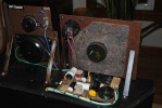
I ran into my first question. Bob had warned someone in another post about the cloth leads color fading over time. This picture shows the other amps wiring to the speaker output. According to the manual pin 1 on the bottom is Black, then brown, orange, and yellow. The 16 ohm tap (4 yellow?) seems to have a thinner gauge wire. There is also an unused wire with the shrink tube covering the end that looks brown. Both amps were wired the same. I just wanted to confirm if this looks wired right or if someone has monkeyed with it. Also, what is that unused wire?

Thanks,
Jim
Thanks,
Jim
Luddite- Posts : 233
Join date : 2009-02-04
Age : 73
Location : Texas
harpy wrote: ...Also, what is that unused wire?
Thanks,
Jim
There was an optional version of the MKIII with provision for a 70.7V (constant voltage) output, which is used in commercial distributed sound systems. That may explain the extra transformer lead.
Best Regards,
Charlie
harpy- Posts : 94
Join date : 2012-02-04
Interesting Thanks. The transformers are back on with Dynakit’s isolation mounts, but larger head bolts. I decided not to paint the cores or covers. Cleaned covers with Hoppes 9 Solvent after trying something milder then wiped some WD 40 to protect areas that had been damaged.
Wiring up the transformers was a pain. The Teflon shrink tubing made the leads harder to work with and the old wires were brittle if you played with them too much. We shall see I guess.


Wiring up the transformers was a pain. The Teflon shrink tubing made the leads harder to work with and the old wires were brittle if you played with them too much. We shall see I guess.

heyraz- Posts : 59
Join date : 2011-10-26
You might want to measure the resistances between the different wires on the transformer's secondary side to verify the taps. Also--Is that a rectifier stack I see bolted in the photo? Is it original? I thought they were unreliable.

GP49- Posts : 792
Join date : 2009-04-30
Location : East of the sun and west of the moon
They ARE unreliable. However, selenium rectifiers' failure mode is high resistance or open, and even when they work, silicon diodes have a lower forward resistance, so bridging a silicon diode across a selenium rectifier, using the original selenium device as a "terminal strip," works just fine. In the photo I see what MIGHT be such a silicon diode, just so mounted on the selenium rectifier.
harpy- Posts : 94
Join date : 2012-02-04
Yes, that's how both were wired, bridged with diodes that were not original. The selenium rectifier uses a different resistor value than the diode on the two post board setup (1000 ohm verse 4700 ohm). I decided to remove selenium rectifier and go with the two post board set up mainly for my ease of understanding. Thanks for bringing those points up.
Installed the 4700 ohm resistor, diode, .02 Uf, and Vishay 100uf caps.


Installed the 4700 ohm resistor, diode, .02 Uf, and Vishay 100uf caps.

Bob Latino- Admin
- Posts : 3263
Join date : 2008-11-26
Location : Massachusetts
Getting rid of a selenium rectifier and replacing it with a diode is a good thing to do. As GP49 has said, they are unreliable and their unreliability increases with age. Selenium is also a bad poison. When a selenium rectifier starts to go usually the resistance increases and the forward voltage starts to drop sometimes making biasing difficult. I have never been around or seen one actually fail right in front of me but I had an old timer tube enthusiast tell me that he was working on an amp one time when the selenium rectifier blew. He said that the destruction produced a real "stink" from bad fumes given off during the destruction. He opened the windows to ventilate the area and even at that he said that the fumes made his eyes water and burned his nasal passages.
Moral > Replace all selenium rectifiers in all original Dynaco amps (ST-70, Mark II, Mark III and Mark IV) with a diode ... Any diode will do. That selenium rectifier is for the bias system only and only looks at about 50 to 55 VAC.
Bob
Moral > Replace all selenium rectifiers in all original Dynaco amps (ST-70, Mark II, Mark III and Mark IV) with a diode ... Any diode will do. That selenium rectifier is for the bias system only and only looks at about 50 to 55 VAC.
Bob
harpy- Posts : 94
Join date : 2012-02-04
I had no idea, thanks Bob. When I looked at the manual with the plus and the minus I thought it was just a terminal and the diode was supposed to be there. I switched to back to manual 929003-2 that has the diode setup. I am having fun doing the steps.
I had to correct my speaker output wiring. I think the wire connected to the 16 ohm tap was the white commercial wire. These amps may have been used commercially, but did not have the 5 output terminal strip. They both had slots cut in each cage too. Ohmed out the output transformers per Bob's guide and it checked out O.K. Metered the SDS Labs Board got good Uf readings at the coupling caps. Installed quad cap board. Wasn't sure the best way to route the Cathode wire. Decided to run it high so at least is not resting on any other wires. All wiring are mounted from underneath the SDS board.

I had to correct my speaker output wiring. I think the wire connected to the 16 ohm tap was the white commercial wire. These amps may have been used commercially, but did not have the 5 output terminal strip. They both had slots cut in each cage too. Ohmed out the output transformers per Bob's guide and it checked out O.K. Metered the SDS Labs Board got good Uf readings at the coupling caps. Installed quad cap board. Wasn't sure the best way to route the Cathode wire. Decided to run it high so at least is not resting on any other wires. All wiring are mounted from underneath the SDS board.
harpy- Posts : 94
Join date : 2012-02-04
Dynakit's Bias Balance Control Kit wired up.

harpy- Posts : 94
Join date : 2012-02-04
Ok first don't laugh, but would these have any hope of not melting? I could mount them at the edge of the board well away from the tube socket. Is it a bad application for them? I was just going to use the Dynakit ones, but found these and was curious.

harpy- Posts : 94
Join date : 2012-02-04
Wired up except for the resistor that goes across the speaker terminals. I removed it and redid the speaker terminals. I fired it up and all the tubes lit and I checked some voltages. First problem was the power transformer hummed, so I replace the GZ-34 and it went away. I hooked up to a small speaker and my goodness the hum was horrible. That was corrected by properly grounding the SDS board. Bought the wrong resister value for the speaker terminals, so I'll have to wait for round two to see what I else I have done wrong and test some more. Really dig the Dynakit parts they really do a nice job with their products. Their documentation is outstanding, wish the SDS Board was even close to the same level.

harpy- Posts : 94
Join date : 2012-02-04
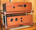
Top side view.

Dynakit's PCB with the Jupiter caps soldered in and NOS RCA 6an8a. I will see if they melt and change if necessary.

Genalex KT88 and GZ-34 installed. Think I put on the output transformer cover on backwards, but I am not going to pull it out to correct. Still have to bias the tubes out and do the second amp if this continues to check out.
Dynakit's PCB with the Jupiter caps soldered in and NOS RCA 6an8a. I will see if they melt and change if necessary.
Genalex KT88 and GZ-34 installed. Think I put on the output transformer cover on backwards, but I am not going to pull it out to correct. Still have to bias the tubes out and do the second amp if this continues to check out.
harpy- Posts : 94
Join date : 2012-02-04
Decided the transformers looked too shabby and they needed paint. The black transformers were painted with a can of Rust-Oleum High Heat paint. It was thinned with Mineral Spirits and airbrushed on, so it didn't clog the panels. The Bells were sanded to bare metal then painted with Dark Grey Enamel and baked in the oven at 350 degrees for 30 minutes. They were left in the oven for about 4 hours allowing them to cool back down to room temperature. They are a bit lighter than the originals, but pretty close. Both have Z280 output transformers with the extra output wires.

danf- Posts : 58
Join date : 2009-01-19
Mark IIIs get quite hot - I'd keep an eye on those wax caps.
Best,
Dan
Best,
Dan
harpy- Posts : 94
Join date : 2012-02-04
Dan,
I ran the amp for 3 hours and they started to get pretty glossy. I tapped the ends with a dental pick and they were pretty soft, so I don't think they will work. If I researched better I would have found they should never be installed where temperatures exceed 110 degrees Fahrenheit. I think what I am going to do is cut the copper leads off and replace tem with wicks and either use them for my Niece next Birthday cake or in my shrine to stupidity.
I ran the amp for 3 hours and they started to get pretty glossy. I tapped the ends with a dental pick and they were pretty soft, so I don't think they will work. If I researched better I would have found they should never be installed where temperatures exceed 110 degrees Fahrenheit. I think what I am going to do is cut the copper leads off and replace tem with wicks and either use them for my Niece next Birthday cake or in my shrine to stupidity.
danf- Posts : 58
Join date : 2009-01-19
Hi Harpy,
Are those Jupiters of recent manufacture? They look like something you'd find in an antique radio.
I used Solens and I didn't like how hot they were getting so I moved them to the underside of the board.
Best,
Dan
Are those Jupiters of recent manufacture? They look like something you'd find in an antique radio.
I used Solens and I didn't like how hot they were getting so I moved them to the underside of the board.
Best,
Dan
Last edited by danf on Tue Jun 05, 2012 6:20 am; edited 1 time in total
harpy- Posts : 94
Join date : 2012-02-04
Those caps aren't made anymore, but they are fairly recent manufacture. These were from Jupiter's Vintage series. I had got these mixed up with another one of their other products. Their newer wax caps are encased in paper and are good to 185 degrees. I will play with these a little more then put the Dynakit ones in. I do love it when they heat up and start to get really glossy, but it would just be a matter of time figuring out how to get the wax off the PCB.
harpy- Posts : 94
Join date : 2012-02-04
The candle sticks were removed and K40-Y9 were installed and the finally the second amp is finally built.

The Dynakit board has two solder points for each cap, so I put some high temp double sided foam tape over the inner hole so the metal bodies of the K40's wouldn't touch the contact.
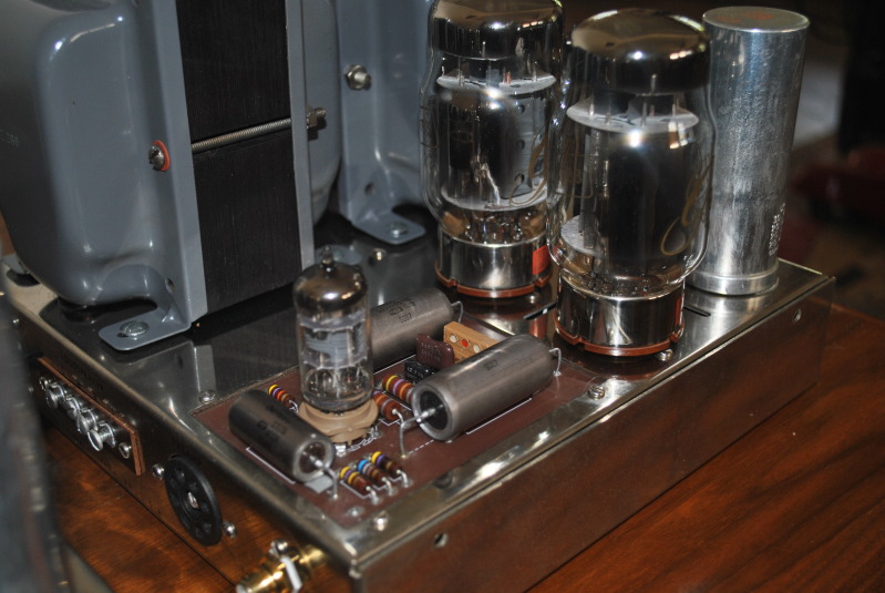
K40's installed.

Shot of both amps.
I built both by the manual and they retain the stock circuit, with the exception of the SDS Labs quad cap board, but that only gives more capacitance. The only original parts are the transformers, the chassis, power cords, and fuse holders. The rest of the parts are from Dynakit with the exception of the SDS board. There was a build error in the first amp. The bias resistors were the wrong value (stock 11.2 ohm instead of the 10 ohms that came with the dual bias kit.

My line in voltage was 121 Vac which probably would be fine, but I added a soft start and voltage bucker which knocks it down about 3 Vac. I measured the voltages of both amps and they were pretty much spot on.
My speakers are DQ-10's crossed over at about 60 Hz and are not an easy speaker to drive. I drove the amps pretty hard for 4 hours, both power transformers were 133.3 degrees F after the session. I was surprised how much different they sounded from the MkIV's they replaced. I thought the MkIV's had a sweeter sound, larger sound stage, while the MKIII's were faster, more dynamic, and detailed (both stock circuit with similar caps). The problem with the MKIV's was they were under powered for the DQ-10's and ran very hot and lacked the punch for demanding music at volume.
I want to listen to the MkIII’s for a bit and make sure no problems arise and get to know their sonics better. After that I may try the Russian Teflon Caps to see if I can hear difference between the coupling caps and then down road start looking at VTA driver boards.
The Dynakit board has two solder points for each cap, so I put some high temp double sided foam tape over the inner hole so the metal bodies of the K40's wouldn't touch the contact.
K40's installed.
Shot of both amps.
I built both by the manual and they retain the stock circuit, with the exception of the SDS Labs quad cap board, but that only gives more capacitance. The only original parts are the transformers, the chassis, power cords, and fuse holders. The rest of the parts are from Dynakit with the exception of the SDS board. There was a build error in the first amp. The bias resistors were the wrong value (stock 11.2 ohm instead of the 10 ohms that came with the dual bias kit.
My line in voltage was 121 Vac which probably would be fine, but I added a soft start and voltage bucker which knocks it down about 3 Vac. I measured the voltages of both amps and they were pretty much spot on.
My speakers are DQ-10's crossed over at about 60 Hz and are not an easy speaker to drive. I drove the amps pretty hard for 4 hours, both power transformers were 133.3 degrees F after the session. I was surprised how much different they sounded from the MkIV's they replaced. I thought the MkIV's had a sweeter sound, larger sound stage, while the MKIII's were faster, more dynamic, and detailed (both stock circuit with similar caps). The problem with the MKIV's was they were under powered for the DQ-10's and ran very hot and lacked the punch for demanding music at volume.
I want to listen to the MkIII’s for a bit and make sure no problems arise and get to know their sonics better. After that I may try the Russian Teflon Caps to see if I can hear difference between the coupling caps and then down road start looking at VTA driver boards.
Similar topics
|
|
|