The Dynaco Tube Audio Forum

Would you like to react to this message? Create an account in a few clicks or log in to continue.
The Dynaco Tube Audio Forum

Dedicated to the restoration and preservation of all original Dynaco tube audio equipment - Customer support for Tubes4hifi VTA tube amp and preamp kits and all Dynakitparts.com products


+2
Sprags
turbotoy
6 posters

    PH16 Pictures

    avatar
    turbotoy


    Posts : 48
    Join date : 2012-04-15

    PH16 Pictures Empty PH16 Pictures

    Post by turbotoy Fri May 03, 2013 10:47 am

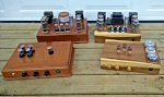
    Here are some photos of Roy's PH16 kit that I just completed. I'm coming from a PH12/SP12 combo. I wanted to go to a separate phono stage to 1) not burn up extra tubes when I'm not listening to vinyl, 2) unburden the SP12 power supply and 3) attempt to reduce power supply noise that existed in the PH12 (not that it was bad). When Roy announced the PH16 I figured I would take "the plunge." The kit went together easily as usual for Roy's products. Sonics are clearly improved over the PH12; I'm hearing more detail. Measured gain is 57 dB, so I reconfigured my SUT to a 5:1 turns ratio for a total system gain of 71 dB. This is about right for the low output MC Denon 103R cartridge I'm using per calculations. In practice, I'm getting output levels that are about the same as my CD player, so it's probably a touch high.

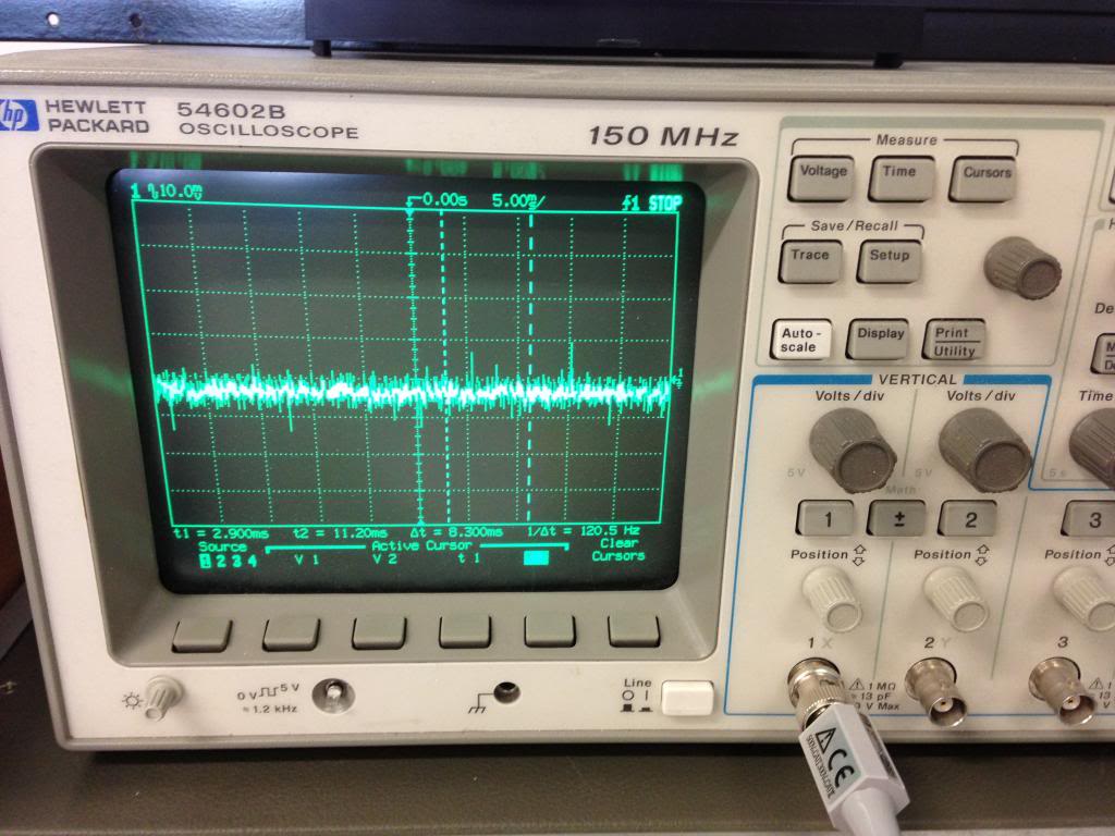
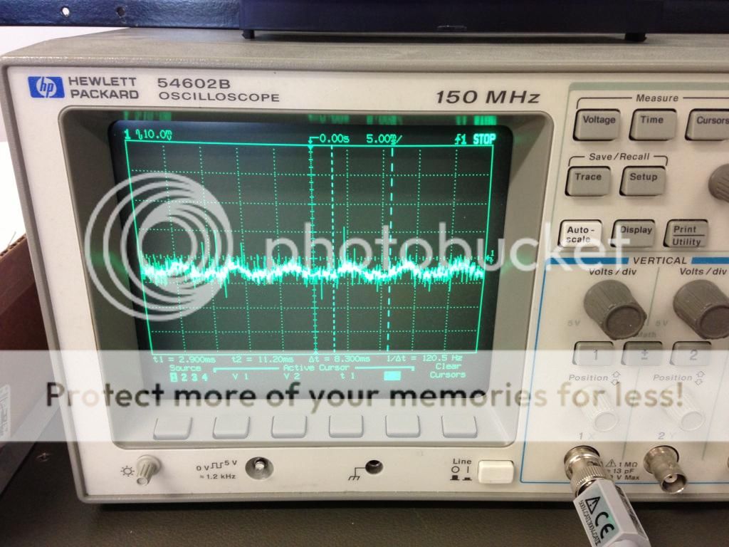
    I do have some power supply noise (clearly 120 Hz so it's from the B+) that's a little worse than I had with the PH12. This may be totally because I went from a 20:1 turns ratio on the SUT with the PH12 to 5:1 with the PH16, so the incoming S/N ratio is worse. The 120 Hz hum isn't audible at normal program volume however, just with the volume turned up to "loud." If Roy or Troy reads this I would be interested in comparing some measured voltages/ripple values to make sure my regulators on the phono board are actually regulating correctly as I'm not positive about that.

    All in all, I'm very very happy, especially when value for money is considered!

    PH16 Pictures DSC_0686

    PH16 Pictures DSC_0687

    PH16 Pictures DSC_0689
    avatar
    Sprags


    Posts : 123
    Join date : 2013-02-27

    PH16 Pictures Empty Re: PH16 Pictures

    Post by Sprags Fri May 03, 2013 11:56 am

    Very nice build!

    Where did you get that chassis, cover and faceplate.
    avatar
    turbotoy


    Posts : 48
    Join date : 2012-04-15

    PH16 Pictures Empty Re: PH16 Pictures

    Post by turbotoy Fri May 03, 2013 12:23 pm

    Sprags wrote:Very nice build!

    Where did you get that chassis, cover and faceplate.

    I knew that would be quickly asked. You won't believe this. It's the chassis to a Drake ESR1824 C/KU-Band satellite receiver - do a google image search. I was going to throw it in the trash years ago since analog satellite has virtually disappeared and it's truly worthless, but decided to hang onto it.

    For the faceplate I cut out the areas where the buttons were and then then painted it black. I then made the aluminum insert that the power switch is mounted to (jigsaw/file work, I really need a Bridgeport). I sanded/polished the tinted/translucent center panel that used to have a bunch of print on it for the LED indicators for the receiver so it's now a tinted window into the preamp. The rectifier tube is dead center and glows nicely through the window along with the other tubes. I made a replacement rear panel obviously from some scrap aluminum. The original satellite receiver had its transformers bolted to the standoffs where I have the new ones mounted, I just needed to make up plates to mount the torroids.

    At first I wasn't sure I was going to like the outcome... However, for free, I am very happy with how it turned out!
    avatar
    Sprags


    Posts : 123
    Join date : 2013-02-27

    PH16 Pictures Empty Re: PH16 Pictures

    Post by Sprags Fri May 03, 2013 12:35 pm

    Hmmm....now I know what to do with my Betamax VCR.
    avatar
    turbotoy


    Posts : 48
    Join date : 2012-04-15

    PH16 Pictures Empty Re: PH16 Pictures

    Post by turbotoy Thu May 09, 2013 9:16 pm

    Well, I have a real lack of understanding of my power supply issue that I am hoping I can get some help with from you folks. I realize no one is really familiar with this circuit, but it should be basic power supply principals. The power supply has two voltage regulators. Output directly from these two regulators supplies B+ to the two output buffer tubes, one B+ for each channel. An RC filter is then coupled to the output of each voltage regulator, which supplies the B+ for V1/V2, the first and second stages, again one for each channel. The design intent here is to apply additional filtering to the very sensitive initial stages.

    Now here's where things get weird. If I measure the AC component of the voltage, I get about 0.3 mV RMS coming directly out of the regulator. However, after the RC filter this value is about 1.1 mV RMS! Same results for both regaultors/channels. If I hook the B+ supplies up the intended way I get much more 120 Hz hum than if I hook them up "backwards." Yesterday I unsoldered the filter capacitors so I just have the voltage out of the regulator and some drop over a 1k resistor. This significantly improved 120 Hz hum, but I know things are not right and can be improved. Besides, I need to understand why this is happening!

    The big question is why does the presence of the filter capacitor introduce more B+ ripple?? The only way I can see this being possible is if the ground that the capacitor is tied to actually has ripple. Why that would be, I do not know, but I've postulated that it *could* be from an unbalance in the voltage doubler. I have a scope, but I'm having a hard time getting good noise-free signals at these low ripple voltages, I'm sure because of my lack of experience/measurement technique. The DMM AC voltage method seems to be reasonable for relative assessments, but I relaize it means nothing in absolute terms. However, with the filter caps removed I now measure about 1.4 mV RMS on one channel and 2.4 mV RMS on the other channel at the output of the phono stage. The difference could be tied to the asymmetry of one of the B+ voltage regulators being used to lift the heater supply potential. Other than that, I don't know why they would be different.

    I would certainly apprecaite any suggestions and/or things to check to help diagnose this. In the absence of anything else, I was thinking about using a choke in each B+ supply to V1/V2 as that's a filtering method that does not require reference to ground. However, there may be other issues going on (like ripple being induced in the CCS) if the ground has ripple, so my instinct is to try to determine and fix the root cause first.


    Last edited by turbotoy on Thu May 09, 2013 9:19 pm; edited 1 time in total (Reason for editing : Fix typo.)
    Zimmer64
    Zimmer64


    Posts : 123
    Join date : 2013-01-29
    Age : 60
    Location : Switzerland

    PH16 Pictures Empty Re: PH16 Pictures

    Post by Zimmer64 Fri May 10, 2013 2:05 am

    Hi,

    Just a thought. You twisted all cables nicely except the signal input coming from the RCA's. The hum of my last amplifier build was caused by this. I even had to use shielded cable on one channel to get rid of the hum.

    Best

    Michael
    avatar
    turbotoy


    Posts : 48
    Join date : 2012-04-15

    PH16 Pictures Empty Re: PH16 Pictures

    Post by turbotoy Fri May 10, 2013 10:36 am

    Zimmer64 wrote:

    Just a thought. You twisted all cables nicely except the signal input coming from the RCA's. The hum of my last amplifier build was caused by this. I even had to use shielded cable on one channel to get rid of the hum.


    Hello Michael,

    The cables used for all of the signals are actually shielded, which is why they don't appear twisted. The cables I used were scrap s-video cables, which are a nice size/form for this application. Also, if they were picking up hum it should be 60 Hz, not 120 Hz. I can easily induce a ground loop and observe 60 Hz hum. Thank you for the suggestion though.

    Jesse
    avatar
    turbotoy


    Posts : 48
    Join date : 2012-04-15

    PH16 Pictures Empty Re: PH16 Pictures

    Post by turbotoy Fri May 10, 2013 11:51 am

    Here are some pictures of the signals to hopefully help the troubleshooting:

    This is B+1 at the phono board, which comes straight off the voltage regulator. This is basically ripple free.

    PH16 Pictures B1_unfiltered

    This is B+2 at the phono board, which is RC filtered. Note the slight 120 Hz ripple.

    PH16 Pictures B2_RC_filtered

    This is at the output jack, clearly 120 Hz.

    PH16 Pictures Output

    And just for kicks, this is what the "center tap" of the voltage doubler looks like if I lift the connection to chassis ground.

    PH16 Pictures CT_ground_lifted


    Last edited by turbotoy on Fri May 10, 2013 11:54 am; edited 1 time in total (Reason for editing : Fix picture links)
    avatar
    turbotoy


    Posts : 48
    Join date : 2012-04-15

    PH16 Pictures Empty Re: PH16 Pictures

    Post by turbotoy Sat May 11, 2013 12:17 pm

    Wow, getting high gain phono stage power supplies right is tricky business... I simply moved the ground connection (to chassis and the phono board) on the power supply board from the CT holes to the ground trace between the two capacitors that follow the rectifier. This significantly reduced the ripple in B+2 (with the RC filter in place), but introduced ripple coming straight out of the voltage regulators (B+1). Note, this major change was simply from moving the ground connection about 4" along exactly the same trace on the power supply board!

    This change basically made things exactly as they were when I eliminated the filter capacitors from B+2. The right channel has low level 120 Hz hum. The left channel has 120 Hz hum just loud enough to annoy me. If I swap the interconnects at the phono stage the hum switches speakers, as one would expect.

    I think my next approach will be to remove the B+2 RC filter on the power supply board and install 10 uF of capacitance at each one of the B+ connections right at the phono board. This worked well previously on my PH12, I just don't have the caps on hand.

    I wish I had a better understanding of exactly what was happening, but this result confirms it's partially or totally related to the power supply grounding configuration.
    avatar
    turbotoy


    Posts : 48
    Join date : 2012-04-15

    PH16 Pictures Empty Re: PH16 Pictures

    Post by turbotoy Sat May 11, 2013 3:58 pm

    Finally solved. Oh the cruel realities of real circuits. The RC filter for B+2 was tied to a ground trace, and at the end of that trace was the ground connections for the two filter caps coming straight off the rectifier. Well, that ground trace has impedance assocated with it, and it also has non-trivial current flowing through it as the filter caps tied to the rectifer are presented a sawtooth waveform from the rectifier. The result was a changing potential where the very sensitive grounds for the B+2 RC circuit were tied. The solution was to cut the trace and run a jumper from the CT point to the rectifier filter caps. With that done ripple on both B+1 and B+2 is basically unmeasurable. 120 Hz hum is now very much reduced. Some additional capacitance on the phono board would probably make it a little better, but for all practical purposes it's sufficiently quiet, and easily beats my previous PH12 in that department. I was the first one to build one of these version 3 power supplies, so no one else would have run into this issue yet.

    In terms of sonics, I can now enjoy what this phono stage is really capable of, and I am very impressed! I also spent time dialing in the optimal cartridge loading, and ~150 ohms (at the input to the SUT) was found to be the optimal value to keep a square wave sharp. Adding capacitance just made things worse, as expected. The ability to adjust values on the fly with the dip switches really is nice and you can certainly alter the sound. However, what I first thought was optimal by ear was actually ringing when I looked at the scope, and after listening some more the value of 150 ohms that was found to be optimum by measurement really does sound better, particularly when paying attention to sibilance.
    Roy Mottram
    Roy Mottram
    Admin


    Posts : 1837
    Join date : 2008-11-30

    PH16 Pictures Empty Re: PH16 Pictures

    Post by Roy Mottram Mon May 13, 2013 12:35 pm

    thanks to Jesse for his amazing troubleshooting and persistence of getting the power supply as quiet as possible.
    We made 4 of these PCBs so there are 1 or 2 others out there now (Troy is working on one of them) that could benefit from this change,
    which I will incorporate for the next run of PCBs.
    avatar
    turbotoy


    Posts : 48
    Join date : 2012-04-15

    PH16 Pictures Empty Re: PH16 Pictures

    Post by turbotoy Mon May 13, 2013 7:50 pm

    This was actually a GREAT learning experience for me, which was a major reason why I wanted to get into this hobby to begin with. A lesson I have learned time and time again in engineering (all the disciplines) is that success almost never leads to true understanding, only failure and subsequent resolution does (with a lot of pain and learning inbetween).

    Also, don't let this minor issue deter anyone from trying the PH16. The required change does not change the circuit schematic AT ALL. The change is only how the ground connections are physically made. At first glance, it's hard to phathom that such a minor change could make such a big difference. This is the reality of dealing with an active stage with 57 dB of gain; a lot is asked of the power supply.

    I'm now totally thirlled with the performance of this phono stage, it was well worth the time and money. I went with all Russian PIO coupling caps and Amperex tubes this time, and I'm sure that's not hurting things either.

    Now my biggest issue is that I want to go spend more money searching out vinyl to expand my collection!
    gener8r
    gener8r


    Posts : 61
    Join date : 2012-04-28

    PH16 Pictures Empty Re: PH16 Pictures

    Post by gener8r Thu May 16, 2013 6:25 pm

    Thank You for your posts. I'm getting ready to build a PH16, so this is encouraging and helpful.
    avatar
    dhatadi


    Posts : 3
    Join date : 2014-01-13

    PH16 Pictures Empty Re: PH16 Pictures

    Post by dhatadi Sun Jan 19, 2014 12:43 am

    turbotoy wrote:Here are some photos of Roy's PH16 kit that I just completed.

    PH16 Pictures DSC_0689

    Hi turbotoy, I'm building one of these at the moment and it's working very well. But I'd like to experiment with adding a choke. Where exactly does that wire up to? Does it replace R27 on the power supply board? If that's the case, would I need something other than a 155J if I'm using 240V instead of 200V?

    Any help would be appreciated.

    Cheers,
    Daniel
    avatar
    turbotoy


    Posts : 48
    Join date : 2012-04-15

    PH16 Pictures Empty Re: PH16 Pictures

    Post by turbotoy Sun Jan 19, 2014 11:00 am

    dhatadi wrote:

    Hi turbotoy, I'm building one of these at the moment and it's working very well. But I'd like to experiment with adding a choke. Where exactly does that wire up to? Does it replace R27 on the power supply board? If that's the case, would I need something other than a 155J if I'm using 240V instead of 200V?

    Any help would be appreciated.

    Cheers,
    Daniel

    Hello Daniel,

    As you thought, the choke would replace R27 on the power supply board. The DC resistance of the Hammond 155J choke is about 1k, so you'll wind up with about the same B+ at the regulators as you have with the R27 1k resistor in place. In some of my original power supply troubleshooting work I swapped the choke for the resistor and to tell you the truth I couldn't measure any real difference in the ripple going into the regulators, and certainly nothing on the output of the regulators (i.e. you won't hear any difference). The only reason I used the choke was because I had it lying around from when I was using a PH12 in my SP12 chassis. In other words, if you need to buy one, I don't think it's worth it at all. I still have a tiny bit of power supply ripple, but that needs to be addressed after the voltage regulators. I was going to try adding some caps right at the PH16 board, but I haven't felt a pressing need to, which should give you an idea of how quiet it is now Wink I've just been listening.

    Is there any particular reason why you want to try adding the choke (i.e. power supply noise)?

    I'm not sure I follow your question on using 240V vs. 200V. You should have around 250VDC coming from the 12X4 rectifier. The 155J is rated at 400VDC.
    avatar
    dhatadi


    Posts : 3
    Join date : 2014-01-13

    PH16 Pictures Empty Re: PH16 Pictures

    Post by dhatadi Sun Jan 19, 2014 10:52 pm

    I ended up using a transformer with a 240V instead of 200V secondary so I bumped up R27 to 2.2K (if I recall correctly). This was at Roy's suggestion. Which means that the voltage coming from the rectifier is closer to 300V.

    I was having issues with my grounding which made for a 100hz hum that was too loud for my liking. Note that in Australia, we run at 240V 50hz. While I was sorting out my grounding issues I thought I should look into the possibility of a choke but it sounds like that's not worth it.

    Also, I found that my RCA sockets were in contact with the chassis and after I fixed that (and added a chassis ground to the AC input), everything seems to be working very well.

    But out of curiosity, it sounds like I would need a different choke, something that would be closer to 2.2k. Or could I add a resistor in series with the choke?

    Anyway, thanks for you response. I just like learning all this as I go.

    Cheers,
    Daniel
    Roy Mottram
    Roy Mottram
    Admin


    Posts : 1837
    Join date : 2008-11-30

    PH16 Pictures Empty Re: PH16 Pictures

    Post by Roy Mottram Mon Jan 20, 2014 3:52 pm

    the resistor works almost as well as a choke, but yes, if you did use a choke you would either need to find one with a higher DC resistance (I don't think I've seen any with resistance that high) or use one in combination with a resistor, and you could add a cap to ground in between to increase the filtering action,
    but if you are nearly humfree now then it's probably not worth the trouble and expense.
    avatar
    turbotoy


    Posts : 48
    Join date : 2012-04-15

    PH16 Pictures Empty Re: PH16 Pictures

    Post by turbotoy Mon Jan 20, 2014 9:21 pm

    Ahh, I understand the question on voltage now. As Roy already mentioned, either find a choke with the right DC resistance or add a resistor in series with it. I really wouldn't bother though, you probably won't notice the difference if you add the choke, it's after the regulators that you have to get as ripple free as possible.

    Glad to hear you got the other issues sorted out. I also agree that troubleshooting and the subsequent learning is what really makes this a worthwhile hobby!

    avatar
    dhatadi


    Posts : 3
    Join date : 2014-01-13

    PH16 Pictures Empty Re: PH16 Pictures

    Post by dhatadi Mon Jan 20, 2014 11:49 pm

    Hmm, okay. So I did actually order a 155J. I guess I was feeling a little trigger happy that day.

    Which means I could possibly add it to a 1.2K resistor in series to make up the total of 2.2k, is that right?

    turbotoy, have you looked at doing anything to the voltage after the regulators? What sort of strategies are we looking at here?

    Again, very happy with the unit and I have some better tubes on the way, but I like the learning.
    avatar
    turbotoy


    Posts : 48
    Join date : 2012-04-15

    PH16 Pictures Empty Re: PH16 Pictures

    Post by turbotoy Tue Jan 21, 2014 9:19 pm

    If you already have the choke coming I would try it, it won't make anything worse. I was going to put four 10uF caps under the board where each B+ supply comes into the PH16. The purpose is to get the caps right on the power rails with minimum impedance. I did this on my PH12 at Roy's suggestion and it helped reduce PS noise quite a bit, but that was powered off of a SP12 B+ supply. However, the caps have been sitting in a box for a while, so I can't tell you how much it would help on the PH16 yet. My hunch is that would probably get rid of the last bit of PS noise, but it's almost at a level where I can't measure it as-is.

    Sponsored content


    PH16 Pictures Empty Re: PH16 Pictures

    Post by Sponsored content


      Current date/time is Sun May 19, 2024 8:44 pm