The Dynaco Tube Audio Forum

Would you like to react to this message? Create an account in a few clicks or log in to continue.
The Dynaco Tube Audio Forum

Dedicated to the restoration and preservation of all original Dynaco tube audio equipment - Customer support for Tubes4hifi VTA tube amp and preamp kits and all Dynakitparts.com products


+12
colin86325
SnugDynaco
ricohman
Roy Mottram
metlmrk
Mr.Miele
Aljaheejus
vleena
sventube
scsidude2
Hirak
Bob Latino
16 posters

    Dynaco ST-70 PC-3 driver board parts layout - photo ...

    Bob Latino
    Bob Latino
    Admin


    Posts : 3263
    Join date : 2008-11-26
    Location : Massachusetts

    Dynaco ST-70 PC-3 driver board parts layout - photo ... - Page 2 Empty Re: Dynaco ST-70 PC-3 driver board parts layout - photo ...

    Post by Bob Latino Thu Jul 08, 2010 2:52 pm

    Hi,

    The Mark II uses the same board layout as the Mark III which is here > Board layout Mark II/III

    Check with Kevin at Dynakitparts. He should have the board layout for the Mark IV.

    Bob
    Aljaheejus
    Aljaheejus


    Posts : 40
    Join date : 2010-01-03

    Dynaco ST-70 PC-3 driver board parts layout - photo ... - Page 2 Empty Resistor Ratings?

    Post by Aljaheejus Wed Aug 25, 2010 8:44 pm

    Bob Latino wrote:Dynaco never gave a parts layout on their PC-3 driver board for the ST-70. They also never listed the parts that were on the driver board in the main parts list for the amp on page 11 of the ST-70 assembly manual. ....

    Bob,
    Great info and photo for replacing parts on my original board. I don't know from this, however, what the power ratings on the resistors should be. Can you point me in the right direction for either original specs, or your recommendations?
    Thanks,
    David
    Bob Latino
    Bob Latino
    Admin


    Posts : 3263
    Join date : 2008-11-26
    Location : Massachusetts

    Dynaco ST-70 PC-3 driver board parts layout - photo ... - Page 2 Empty Re: Dynaco ST-70 PC-3 driver board parts layout - photo ...

    Post by Bob Latino Wed Aug 25, 2010 9:30 pm

    Hi,

    The 270K, smaller 18K, 620 ohm, 47 ohm, 1.5 meg and 10 ohm are all 1/2 watt resistors. All the other resistors on the board are 1 watt. I recommend metal film resistors since they are quiet, don't change their values over time and can be had in 1% values so that the two channels can be closely matched.

    Bob
    Mr.Miele
    Mr.Miele


    Posts : 6
    Join date : 2011-01-26

    Dynaco ST-70 PC-3 driver board parts layout - photo ... - Page 2 Empty Re: Dynaco ST-70 PC-3 driver board parts layout - photo ...

    Post by Mr.Miele Sat Feb 05, 2011 8:04 pm

    Bob, can you let me know dimensions of st70 without cage please. I have about 6 1/4" opening in my shelf. Hope this unit can fit.
    Thanks!
    Bob Latino
    Bob Latino
    Admin


    Posts : 3263
    Join date : 2008-11-26
    Location : Massachusetts

    Dynaco ST-70 PC-3 driver board parts layout - photo ... - Page 2 Empty Re: Dynaco ST-70 PC-3 driver board parts layout - photo ...

    Post by Bob Latino Sat Feb 05, 2011 9:44 pm

    Hi,

    The amp is just about 6 1/4 inches high but I would not place the amp in any small space where there would be restricted air flow. These amps should "look at the ceiling" IMHO. Placing the amp in a confined space can cause the amp to run hot and could damage the power transformer.

    Bob
    Mr.Miele
    Mr.Miele


    Posts : 6
    Join date : 2011-01-26

    Dynaco ST-70 PC-3 driver board parts layout - photo ... - Page 2 Empty Re: Dynaco ST-70 PC-3 driver board parts layout - photo ...

    Post by Mr.Miele Wed Apr 06, 2011 11:23 pm

    This is how my project looks now..

    Dynaco ST-70 PC-3 driver board parts layout - photo ... - Page 2 IMG_1354

    Dynaco ST-70 PC-3 driver board parts layout - photo ... - Page 2 IMG_1344

    Dynaco ST-70 PC-3 driver board parts layout - photo ... - Page 2 IMG_1343
    Bob Latino
    Bob Latino
    Admin


    Posts : 3263
    Join date : 2008-11-26
    Location : Massachusetts

    Dynaco ST-70 PC-3 driver board parts layout - photo ... - Page 2 Empty Re: Dynaco ST-70 PC-3 driver board parts layout - photo ...

    Post by Bob Latino Tue Apr 12, 2011 2:18 pm

    The original Dynaco ST-70 PC-3 board was 6 1/2 inches long by 3 1/4 inches wide.

    Bob
    avatar
    metlmrk


    Posts : 9
    Join date : 2011-06-23

    Dynaco ST-70 PC-3 driver board parts layout - photo ... - Page 2 Empty Feedback on this upgrade

    Post by metlmrk Thu Sep 29, 2011 8:19 am

    Hi, I realise this is an old thread. I am considering updating the coupling caps as noted (.22 & .1) I was hoping that I could get some opinions from people who have done this! Please let me know the pros and cons. The bottom line is it worth doing? Does the sound improve. Can anyone define "improved bass responce" = deeper or tighter bass or...?

    thanks in advance, Mark

    Roy Mottram
    Roy Mottram
    Admin


    Posts : 1839
    Join date : 2008-11-30

    Dynaco ST-70 PC-3 driver board parts layout - photo ... - Page 2 Empty Re: Dynaco ST-70 PC-3 driver board parts layout - photo ...

    Post by Roy Mottram Thu Sep 29, 2011 5:43 pm

    is it worth doing? That's a totally subjective topic. Each person hears things differently.
    I recommend you start with a reasonably priced upgrade, like 716P capacitors, under $2 each.
    Some people like Solens for about the same price (brighter sound, not as warm).
    A high percentage of people really like the russian PIO caps we have on our website, for around $6 each.
    I'm a big believer in value for the $$.
    Other people can't live with anything less than $75 (each piece) Mundorf caps.
    avatar
    metlmrk


    Posts : 9
    Join date : 2011-06-23

    Dynaco ST-70 PC-3 driver board parts layout - photo ... - Page 2 Empty Link

    Post by metlmrk Thu Sep 29, 2011 8:23 pm

    Hi, thanks for your input. Can you give me a link to this site that sell the PIO Caps?

    Regards, Mark
    avatar
    ricohman


    Posts : 11
    Join date : 2012-12-24

    Dynaco ST-70 PC-3 driver board parts layout - photo ... - Page 2 Empty Re: Dynaco ST-70 PC-3 driver board parts layout - photo ...

    Post by ricohman Thu Aug 08, 2013 10:07 pm

    Lots of great info here.
    While I would like to hear an ST-70 the way it came from the factory, I am open to the VTA70 board.
    I have newer mono blocks and the ST-70 is really more of a restoration project. I just don't know how I should proceed.
    Repopulate the board, replace the can, caps and resistors?
    Or go all in for better sound?
    Roy Mottram
    Roy Mottram
    Admin


    Posts : 1839
    Join date : 2008-11-30

    Dynaco ST-70 PC-3 driver board parts layout - photo ... - Page 2 Empty Re: Dynaco ST-70 PC-3 driver board parts layout - photo ...

    Post by Roy Mottram Sun Aug 11, 2013 1:25 pm

    ST70 upgrades on this page here:   ST70 upgrades
    for restoration, replace the quad cap as well as all caps in the amp and on the board.
    For a major upgrade that is easy to do, replace the old Dynaco board with our VTA70 driver board, at the link above
    avatar
    SnugDynaco


    Posts : 26
    Join date : 2011-09-11

    Dynaco ST-70 PC-3 driver board parts layout - photo ... - Page 2 Empty Finished the new ST70 kit, but initial startup did not go well.

    Post by SnugDynaco Sun Mar 23, 2014 10:49 pm

    I really enjoyed the build. All seemed to go very well.

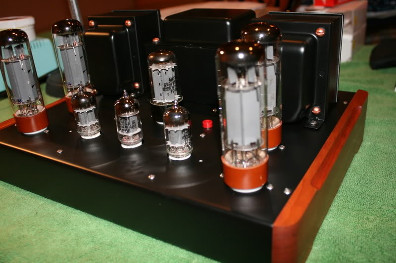
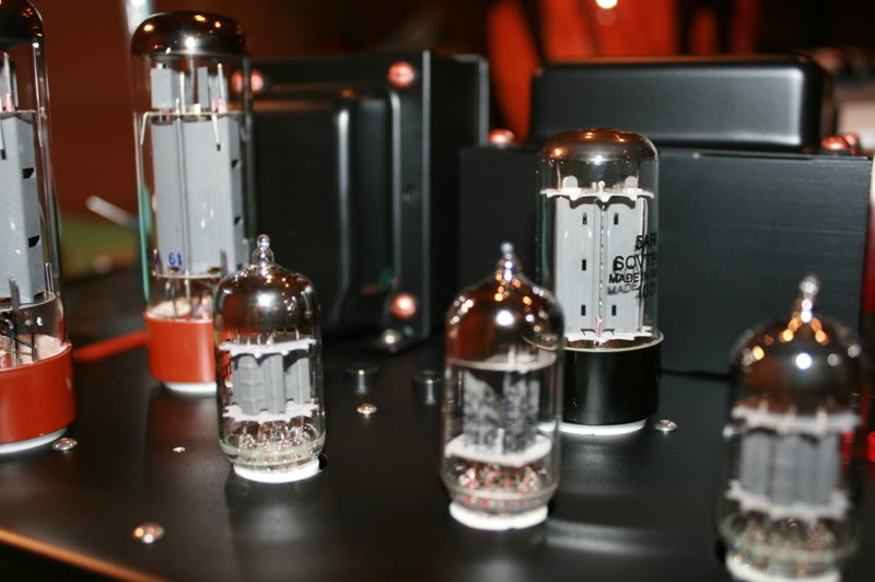
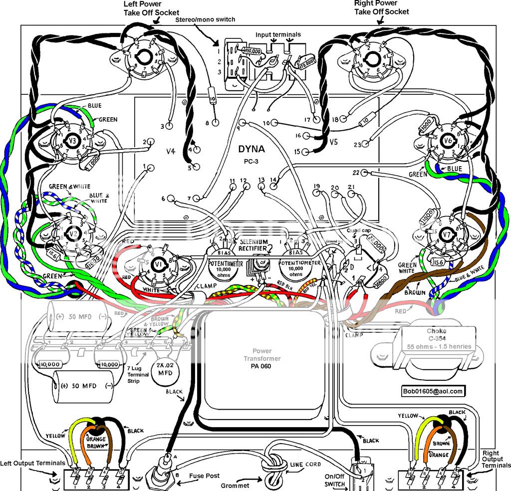
    For the initial startup - following the steps listed in the instructions: first, the three driver tubes lit up as expected. Following the next instructions - connecting the speakers, and installing the rectifier tube and the LEFT side only EL34 tubes. When I applied power the V3 and V2 tubes both lit, but the V2 tube then began to glow intensely, significantly brighter than the V3 tube. After about 5-10 seconds - ever brightening, I shut down the power. The fuse did not blow. Each of the bias adjusting screws was set in the 12-6 o'clock position.

    I have since reopened the bottom and have checked all of the wiring and soldier joints. All seems to be correct. I did not swap the tubes to see if maybe there was something amiss with the "bright" tube.

    The second time around, I first turned the two left bias pots all the way counter-clockwise, to reduce voltage to a minimum. Still the V2 tube was significantly brighter than V3.

    So, what now my friends?

    Paul


    Roy Mottram
    Roy Mottram
    Admin


    Posts : 1839
    Join date : 2008-11-30

    Dynaco ST-70 PC-3 driver board parts layout - photo ... - Page 2 Empty Re: Dynaco ST-70 PC-3 driver board parts layout - photo ...

    Post by Roy Mottram Mon Mar 24, 2014 12:01 pm

    is your center tube the exact same brand and type as the other two driver tubes? All tubes are built differently, on some tubes you can't even see the filaments at all.
    avatar
    colin86325


    Posts : 61
    Join date : 2014-04-01

    Dynaco ST-70 PC-3 driver board parts layout - photo ... - Page 2 Empty Re: Dynaco ST-70 PC-3 driver board parts layout - photo ...

    Post by colin86325 Mon Oct 27, 2014 4:05 pm

    Bob Latino wrote:
    scsidude2 wrote:Thanks for all the help Bob, i just installed the new caps and it sounds great! I was wondering what your recommendation was for the two 50 MFD caps on the terminal strip under the right channel output transformer as to what would be a good upgrade for them? Thanks again! -Ryan

    Hi Ryan,

     I think you mean the 7 lug terminal strip under the LEFT output transformer.

     Those 50 uF caps on the 7 lug terminal strip are only looking at maybe 70 VDC. Any two 47 to 50 uF electrolytic caps at 100 volts or higher would work fine here. Just make sure that you have the polarity correct on these two caps. The "+" end of each cap goes to lug 1 and on the two "-" ends, one goes to lug 3 and one to lug 4. See pictorial below ...
    Bob


    Dynaco ST-70 PC-3 driver board parts layout - photo ... - Page 2 ST-70pictorialHI-REZwithcolor_10-1


    For the two 50MFD caps, will it be ok to replace these with two 80MDF @ 450 VDC caps?
    The amp is using SS rectification.

    avatar
    GP49


    Posts : 792
    Join date : 2009-04-30
    Location : East of the sun and west of the moon

    Dynaco ST-70 PC-3 driver board parts layout - photo ... - Page 2 Empty Re: Dynaco ST-70 PC-3 driver board parts layout - photo ...

    Post by GP49 Wed Oct 29, 2014 10:17 am

    Yes, those will be fine. Higher working voltage will be no problem. The main solid state rectification doesn't make any difference either, since the bias voltage supply is independent, running off its own winding on the power transformer and with its own rectifier (hopefully you are not still running the original selenium rectifier).

    Present day capacitors are much smaller than the originals, so it is easy to fit larger value parts.
    avatar
    colin86325


    Posts : 61
    Join date : 2014-04-01

    Dynaco ST-70 PC-3 driver board parts layout - photo ... - Page 2 Empty Re: Dynaco ST-70 PC-3 driver board parts layout - photo ...

    Post by colin86325 Thu Oct 30, 2014 9:02 am

    Thanks GP49!

    Incidentally, I came across the Van Alstine article, which had this to say about keeping the bias caps at a maximum of 100uF each:
    Do not use a larger capacitor in this application or the supply will come up too slowly, over-biasing the output tubes at turn on.
    avatar
    alyosha


    Posts : 32
    Join date : 2012-04-23

    Dynaco ST-70 PC-3 driver board parts layout - photo ... - Page 2 Empty Re: Dynaco ST-70 PC-3 driver board parts layout - photo ...

    Post by alyosha Fri Feb 06, 2015 4:32 am

    Hi,
    Just one question regarding replacement of the resistors on the PC-3 as I'm building one from scratch, would these be 1/2W, 1W, 2W? Thanks.
    Best regards.
    WireNut
    WireNut


    Posts : 67
    Join date : 2017-02-21
    Location : Twin Cities

    Dynaco ST-70 PC-3 driver board parts layout - photo ... - Page 2 Empty Re: Dynaco ST-70 PC-3 driver board parts layout - photo ...

    Post by WireNut Thu Feb 23, 2017 5:30 pm

    The amp that is due to arrive tomorrow has the SDS Labs board, can I/should I up the coupling cap value to 2.2 like was suggested earlier on this post? If so, should I increase the .47 to 1.0?
    Bob Latino
    Bob Latino
    Admin


    Posts : 3263
    Join date : 2008-11-26
    Location : Massachusetts

    Dynaco ST-70 PC-3 driver board parts layout - photo ... - Page 2 Empty Re: Dynaco ST-70 PC-3 driver board parts layout - photo ...

    Post by Bob Latino Thu Feb 23, 2017 7:39 pm

    WireNut wrote:The amp that is due to arrive tomorrow has the SDS Labs board, can I/should I up the coupling cap value to 2.2 like was suggested earlier on this post? If so, should I increase the .47 to 1.0?

    You can increase the capacitance on the four coupling caps at least up to .22 uF with no issues > not the 2.2 uF that you mention above.

    Bob
    WireNut
    WireNut


    Posts : 67
    Join date : 2017-02-21
    Location : Twin Cities

    Dynaco ST-70 PC-3 driver board parts layout - photo ... - Page 2 Empty Re: Dynaco ST-70 PC-3 driver board parts layout - photo ...

    Post by WireNut Thu Feb 23, 2017 7:49 pm

    Ooops, I meant .22, thanks for the advice and correction!
    What about the two .47?
    Bob Latino
    Bob Latino
    Admin


    Posts : 3263
    Join date : 2008-11-26
    Location : Massachusetts

    Dynaco ST-70 PC-3 driver board parts layout - photo ... - Page 2 Empty Re: Dynaco ST-70 PC-3 driver board parts layout - photo ...

    Post by Bob Latino Thu Feb 23, 2017 8:50 pm

    WireNut wrote:Ooops, I meant .22, thanks for the advice and correction!
    What about the two .47?

    You don't really need anything that large .. A .47 might be OK but I would not use it .. Read the 3 links below ..

    Audibility of coupling capacitor changes ..

    And a clarification by Jim McShane who can explain this in more detail ..

    Jim McShane post from August of 2012

    If the cap is TOO big you may run into what is called "blocking distortion". Read about blocking distortion at the link below ...

    Blocking distortion

    Bob
    dmagazz
    dmagazz


    Posts : 147
    Join date : 2018-06-20
    Age : 56
    Location : new fairf, ct

    Dynaco ST-70 PC-3 driver board parts layout - photo ... - Page 2 Empty Re: Dynaco ST-70 PC-3 driver board parts layout - photo ...

    Post by dmagazz Mon Jun 25, 2018 1:38 pm

    thanks for that bob, i have ordered from dynakitparts.com all the caps to replace the old ones in mine.
    also the 80,40,20,20 525v can
    i got a bios kit in an envelope off ebay for $8 thinking it was a actual old stock dynaco kit, i may have been bamboozled. so i may have to reorder that from dyna.

    Sponsored content


    Dynaco ST-70 PC-3 driver board parts layout - photo ... - Page 2 Empty Re: Dynaco ST-70 PC-3 driver board parts layout - photo ...

    Post by Sponsored content


      Current date/time is Fri Apr 26, 2024 11:28 pm